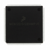
MC912DG128AMPVE Freescale Semiconductor, MC912DG128AMPVE Datasheet - Page 174

MC912DG128AMPVE
Manufacturer Part Number
MC912DG128AMPVE
Description
IC MCU 128K FLASH 8MHZ 112-LQFP
Manufacturer
Freescale Semiconductor
Series
HC12r
Datasheet
1.MC912DG128ACPVER.pdf
(478 pages)
Specifications of MC912DG128AMPVE
Core Processor
CPU12
Core Size
16-Bit
Speed
8MHz
Connectivity
CAN, I²C, SCI, SPI
Peripherals
POR, PWM, WDT
Number Of I /o
69
Program Memory Size
128KB (128K x 8)
Program Memory Type
FLASH
Eeprom Size
2K x 8
Ram Size
8K x 8
Voltage - Supply (vcc/vdd)
4.5 V ~ 5.5 V
Data Converters
A/D 16x8/10b
Oscillator Type
Internal
Operating Temperature
-40°C ~ 125°C
Package / Case
112-LQFP
Processor Series
HC912D
Core
HC12
Data Bus Width
16 bit
Data Ram Size
8 KB
Interface Type
CAN/I2C/SCI/SPI
Maximum Clock Frequency
8 MHz
Number Of Programmable I/os
69
Number Of Timers
8
Maximum Operating Temperature
+ 125 C
Mounting Style
SMD/SMT
3rd Party Development Tools
EWHCS12
Minimum Operating Temperature
- 40 C
On-chip Adc
2 (8-ch x 10-bit)
Lead Free Status / RoHS Status
Lead free / RoHS Compliant
Available stocks
Company
Part Number
Manufacturer
Quantity
Price
Company:
Part Number:
MC912DG128AMPVE
Manufacturer:
FREESCALE
Quantity:
2 902
Company:
Part Number:
MC912DG128AMPVE
Manufacturer:
Freescale Semiconductor
Quantity:
10 000
- Current page: 174 of 478
- Download datasheet (4Mb)
Clock Functions
Technical Data
174
STOP exit without Limp Home
clock monitor disabled
Executing the STOP instruction
STOP exit in Limp Home mode
STOP exit in Limp Home mode
Pseudo-STOP exit in Limp Home
Pseudo-STOP exit
in Limp Home mode without
Pseudo-STOP exit without Limp
Pseudo-STOP exit without Limp
Pseudo-STOP exit without Limp
mode,
without Limp Home mode,
clock monitor enabled
with Delay
without Delay (Fast Stop
Recovery)
mode with Delay
Delay (Fast Stop Recovery)
Home mode, clock monitor
enabled
Home mode, clock monitor
disabled, with Delay
Home mode, clock monitor
disabled, without Delay
Mode
Mode
Table 12-2. Summary of Pseudo STOP Mode Exit Conditions
Table 12-1. Summary of STOP Mode Exit Conditions
. .
Freescale Semiconductor, Inc.
For More Information On This Product,
NOLHM=1
CME=0
DLY=X
NOLHM=1
CME=1
DLY=X
NOLHM=0
CME=X
DLY=1
NOLHM=0
CME=X
DLY=0
NOLHM=0
CME=X
DLY=1
NOLHM=0
CME=X
DLY=0
NOLHM=1
CME=1
DLY=X
NOLHM=1
CME=0
DLY=1
NOLHM=1
CME=0
DLY=0
Conditions
Conditions
Go to: www.freescale.com
Clock Functions
Oscillator must be stable within 4096 XCLK cycles. XCLK
Use of DLY=0 only recommended with external clock.
When a STOP instruction is executed the MCU resets via
Oscillator must be stable within 4096
f
This mode is only recommended for use with an external
CPU exits stop in limp home mode and oscillator running. If
This mode is not recommended as it is possible that the
When a STOP instruction is executed the MCU resets via
Oscillator starts operation following 4096 XCLK cycles
This mode is only recommended for use with an external
VCOMIN
can be modified by SLOW divider register.
the clock monitor reset vector.
the clock monitor circuit can be misled by EXTALi clock
into reporting a good signal before it has fully stabilised
clock source.
the oscillator fails during pseudo-STOP and then recovers
there is a possibility of code runaway as the clock monitor
circuit can be misled by EXTALi clock into reporting a
good signal before it has fully stabilised
initial VCO clock frequency may be high enough to cause
code runaway.
the clock monitor reset vector.
(actual controlled by SLOW mode divider).
clock source.
cycles or there is a possibility of code runaway as
Summary
Summary
MC68HC912DT128A — Rev 4.0
MOTOROLA
Related parts for MC912DG128AMPVE
Image
Part Number
Description
Manufacturer
Datasheet
Request
R
Part Number:
Description:
Manufacturer:
Freescale Semiconductor, Inc
Datasheet:
Part Number:
Description:
Manufacturer:
Freescale Semiconductor, Inc
Datasheet:
Part Number:
Description:
Manufacturer:
Freescale Semiconductor, Inc
Datasheet:
Part Number:
Description:
Manufacturer:
Freescale Semiconductor, Inc
Datasheet:
Part Number:
Description:
Manufacturer:
Freescale Semiconductor, Inc
Datasheet:
Part Number:
Description:
Manufacturer:
Freescale Semiconductor, Inc
Datasheet:
Part Number:
Description:
Manufacturer:
Freescale Semiconductor, Inc
Datasheet:
Part Number:
Description:
Manufacturer:
Freescale Semiconductor, Inc
Datasheet:
Part Number:
Description:
Manufacturer:
Freescale Semiconductor, Inc
Datasheet:
Part Number:
Description:
Manufacturer:
Freescale Semiconductor, Inc
Datasheet:
Part Number:
Description:
Manufacturer:
Freescale Semiconductor, Inc
Datasheet:
Part Number:
Description:
Manufacturer:
Freescale Semiconductor, Inc
Datasheet:
Part Number:
Description:
Manufacturer:
Freescale Semiconductor, Inc
Datasheet:
Part Number:
Description:
Manufacturer:
Freescale Semiconductor, Inc
Datasheet:
Part Number:
Description:
Manufacturer:
Freescale Semiconductor, Inc
Datasheet:


