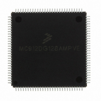
MC912DG128AMPVE Freescale Semiconductor, MC912DG128AMPVE Datasheet - Page 321

MC912DG128AMPVE
Manufacturer Part Number
MC912DG128AMPVE
Description
IC MCU 128K FLASH 8MHZ 112-LQFP
Manufacturer
Freescale Semiconductor
Series
HC12r
Datasheet
1.MC912DG128ACPVER.pdf
(478 pages)
Specifications of MC912DG128AMPVE
Core Processor
CPU12
Core Size
16-Bit
Speed
8MHz
Connectivity
CAN, I²C, SCI, SPI
Peripherals
POR, PWM, WDT
Number Of I /o
69
Program Memory Size
128KB (128K x 8)
Program Memory Type
FLASH
Eeprom Size
2K x 8
Ram Size
8K x 8
Voltage - Supply (vcc/vdd)
4.5 V ~ 5.5 V
Data Converters
A/D 16x8/10b
Oscillator Type
Internal
Operating Temperature
-40°C ~ 125°C
Package / Case
112-LQFP
Processor Series
HC912D
Core
HC12
Data Bus Width
16 bit
Data Ram Size
8 KB
Interface Type
CAN/I2C/SCI/SPI
Maximum Clock Frequency
8 MHz
Number Of Programmable I/os
69
Number Of Timers
8
Maximum Operating Temperature
+ 125 C
Mounting Style
SMD/SMT
3rd Party Development Tools
EWHCS12
Minimum Operating Temperature
- 40 C
On-chip Adc
2 (8-ch x 10-bit)
Lead Free Status / RoHS Status
Lead free / RoHS Compliant
Available stocks
Company
Part Number
Manufacturer
Quantity
Price
Company:
Part Number:
MC912DG128AMPVE
Manufacturer:
FREESCALE
Quantity:
2 902
Company:
Part Number:
MC912DG128AMPVE
Manufacturer:
Freescale Semiconductor
Quantity:
10 000
- Current page: 321 of 478
- Download datasheet (4Mb)
17.7.5 Generation of Repeated START
17.7.6 Slave Mode
MC68HC912DT128A — Rev 4.0
MOTOROLA
be done by setting the transmit acknowledge bit (TXAK) before reading
the 2nd last byte of data. Before reading the last byte of data, a STOP
signal must be generated first. The following is an example showing how
a STOP signal is generated by a master receiver.
At the end of data transfer, if the master still wants to communicate on
the bus, it can generate another START signal followed by another slave
address without first generating a STOP signal. A program example is
as shown.
In the slave interrupt service routine, the module addressed as slave bit
(IAAS) should be tested to check if a calling of its own address has just
been received (see
transmit/receive mode select bit (Tx/Rx bit of IBCR) according to the
R/W command bit (SRW). Writing to the IBCR clears the IAAS
automatically. Note that the only time IAAS is read as set is from the
interrupt at the end of the address cycle where an address match
occurred, interrupts resulting from subsequent data transfers will have
IAAS cleared. A data transfer may now be initiated by writing information
to IBDR, for slave transmits, or dummy reading from IBDR, in slave
RESTART
MASR
LAMAR
ENMASR
NXMAR
Freescale Semiconductor, Inc.
For More Information On This Product,
DEC
BEQ
MOVB
DEC
BNE
BSET
BRA
BCLR
MOVB
RTI
BSET
MOVB
Go to: www.freescale.com
Inter IC Bus
IBCR,#$04
CALLING,IBDR
Figure
RXCNT
ENMASR
RXCNT,D1
D1
NXMAR
IBCR,#$08
NXMAR
IBCR,#$20
IBDR,RXBUF
17-4). If IAAS is set, software should set the
;DECREASE THE RXCNT
;LAST BYTE TO BE READ
;CHECK SECOND LAST BYTE
;TO BE READ
;NOT LAST OR SECOND LAST
;SECOND LAST, DISABLE ACK
;TRANSMITTING
;LAST ONE, GENERATE ‘STOP’ SIGNAL
;READ DATA AND STORE
ANOTHER START (RESTART)
;TRANSMIT THE CALLING ADDRESS
;D0=R/W
IIC Programming Examples
Technical Data
Inter IC Bus
321
Related parts for MC912DG128AMPVE
Image
Part Number
Description
Manufacturer
Datasheet
Request
R
Part Number:
Description:
Manufacturer:
Freescale Semiconductor, Inc
Datasheet:
Part Number:
Description:
Manufacturer:
Freescale Semiconductor, Inc
Datasheet:
Part Number:
Description:
Manufacturer:
Freescale Semiconductor, Inc
Datasheet:
Part Number:
Description:
Manufacturer:
Freescale Semiconductor, Inc
Datasheet:
Part Number:
Description:
Manufacturer:
Freescale Semiconductor, Inc
Datasheet:
Part Number:
Description:
Manufacturer:
Freescale Semiconductor, Inc
Datasheet:
Part Number:
Description:
Manufacturer:
Freescale Semiconductor, Inc
Datasheet:
Part Number:
Description:
Manufacturer:
Freescale Semiconductor, Inc
Datasheet:
Part Number:
Description:
Manufacturer:
Freescale Semiconductor, Inc
Datasheet:
Part Number:
Description:
Manufacturer:
Freescale Semiconductor, Inc
Datasheet:
Part Number:
Description:
Manufacturer:
Freescale Semiconductor, Inc
Datasheet:
Part Number:
Description:
Manufacturer:
Freescale Semiconductor, Inc
Datasheet:
Part Number:
Description:
Manufacturer:
Freescale Semiconductor, Inc
Datasheet:
Part Number:
Description:
Manufacturer:
Freescale Semiconductor, Inc
Datasheet:
Part Number:
Description:
Manufacturer:
Freescale Semiconductor, Inc
Datasheet:


