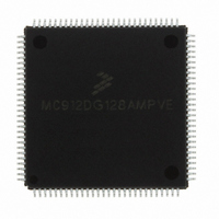
MC912DG128AMPVE Freescale Semiconductor, MC912DG128AMPVE Datasheet - Page 326

MC912DG128AMPVE
Manufacturer Part Number
MC912DG128AMPVE
Description
IC MCU 128K FLASH 8MHZ 112-LQFP
Manufacturer
Freescale Semiconductor
Series
HC12r
Datasheet
1.MC912DG128ACPVER.pdf
(478 pages)
Specifications of MC912DG128AMPVE
Core Processor
CPU12
Core Size
16-Bit
Speed
8MHz
Connectivity
CAN, I²C, SCI, SPI
Peripherals
POR, PWM, WDT
Number Of I /o
69
Program Memory Size
128KB (128K x 8)
Program Memory Type
FLASH
Eeprom Size
2K x 8
Ram Size
8K x 8
Voltage - Supply (vcc/vdd)
4.5 V ~ 5.5 V
Data Converters
A/D 16x8/10b
Oscillator Type
Internal
Operating Temperature
-40°C ~ 125°C
Package / Case
112-LQFP
Processor Series
HC912D
Core
HC12
Data Bus Width
16 bit
Data Ram Size
8 KB
Interface Type
CAN/I2C/SCI/SPI
Maximum Clock Frequency
8 MHz
Number Of Programmable I/os
69
Number Of Timers
8
Maximum Operating Temperature
+ 125 C
Mounting Style
SMD/SMT
3rd Party Development Tools
EWHCS12
Minimum Operating Temperature
- 40 C
On-chip Adc
2 (8-ch x 10-bit)
Lead Free Status / RoHS Status
Lead free / RoHS Compliant
Available stocks
Company
Part Number
Manufacturer
Quantity
Price
Company:
Part Number:
MC912DG128AMPVE
Manufacturer:
FREESCALE
Quantity:
2 902
Company:
Part Number:
MC912DG128AMPVE
Manufacturer:
Freescale Semiconductor
Quantity:
10 000
- Current page: 326 of 478
- Download datasheet (4Mb)
MSCAN Controller
18.3 External Pins
Technical Data
326
The msCAN12 is the specific implementation of the Motorola scalable
CAN (msCAN) concept targeted for the Motorola M68HC12
microcontroller family.
The module is a communication controller implementing the CAN 2.0
A/B protocol as defined in the BOSCH specification dated September
1991.
The CAN protocol was primarily, but not only, designed to be used as a
vehicle serial data bus, meeting the specific requirements of this field:
real-time processing, reliable operation in the EMI environment of a
vehicle, cost-effectiveness and required bandwidth.
msCAN12 utilizes an advanced buffer arrangement resulting in a
predictable real-time behavior and simplifies the application software.
The msCAN12 uses 2 external pins, 1 input (RxCAN) and 1 output
(TxCAN). The TxCAN output pin represents the logic level on the CAN:
0 is for a dominant state, and 1 is for a recessive state.
RxCAN is on bit 0 of Port CAN, TxCAN is on bit 1. The remaining six pins
of Port CAN are controlled by registers in the msCAN12 address space
(see
Port CAN Data Direction Register
A typical CAN system with msCAN12 is shown in
Each CAN station is connected physically to the CAN bus lines through
a transceiver chip. The transceiver is capable of driving the large current
needed for the CAN and has current protection, against defected CAN
or defected stations.
Freescale Semiconductor, Inc.
For More Information On This Product,
msCAN12 Port CAN Control Register (PCTLCAN)
Go to: www.freescale.com
MSCAN Controller
(DDRCAN)).
MC68HC912DT128A — Rev 4.0
Figure 18-1
and
msCAN12
MOTOROLA
below.
Related parts for MC912DG128AMPVE
Image
Part Number
Description
Manufacturer
Datasheet
Request
R
Part Number:
Description:
Manufacturer:
Freescale Semiconductor, Inc
Datasheet:
Part Number:
Description:
Manufacturer:
Freescale Semiconductor, Inc
Datasheet:
Part Number:
Description:
Manufacturer:
Freescale Semiconductor, Inc
Datasheet:
Part Number:
Description:
Manufacturer:
Freescale Semiconductor, Inc
Datasheet:
Part Number:
Description:
Manufacturer:
Freescale Semiconductor, Inc
Datasheet:
Part Number:
Description:
Manufacturer:
Freescale Semiconductor, Inc
Datasheet:
Part Number:
Description:
Manufacturer:
Freescale Semiconductor, Inc
Datasheet:
Part Number:
Description:
Manufacturer:
Freescale Semiconductor, Inc
Datasheet:
Part Number:
Description:
Manufacturer:
Freescale Semiconductor, Inc
Datasheet:
Part Number:
Description:
Manufacturer:
Freescale Semiconductor, Inc
Datasheet:
Part Number:
Description:
Manufacturer:
Freescale Semiconductor, Inc
Datasheet:
Part Number:
Description:
Manufacturer:
Freescale Semiconductor, Inc
Datasheet:
Part Number:
Description:
Manufacturer:
Freescale Semiconductor, Inc
Datasheet:
Part Number:
Description:
Manufacturer:
Freescale Semiconductor, Inc
Datasheet:
Part Number:
Description:
Manufacturer:
Freescale Semiconductor, Inc
Datasheet:


