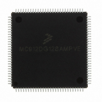
MC912DG128AMPVE Freescale Semiconductor, MC912DG128AMPVE Datasheet - Page 375

MC912DG128AMPVE
Manufacturer Part Number
MC912DG128AMPVE
Description
IC MCU 128K FLASH 8MHZ 112-LQFP
Manufacturer
Freescale Semiconductor
Series
HC12r
Datasheet
1.MC912DG128ACPVER.pdf
(478 pages)
Specifications of MC912DG128AMPVE
Core Processor
CPU12
Core Size
16-Bit
Speed
8MHz
Connectivity
CAN, I²C, SCI, SPI
Peripherals
POR, PWM, WDT
Number Of I /o
69
Program Memory Size
128KB (128K x 8)
Program Memory Type
FLASH
Eeprom Size
2K x 8
Ram Size
8K x 8
Voltage - Supply (vcc/vdd)
4.5 V ~ 5.5 V
Data Converters
A/D 16x8/10b
Oscillator Type
Internal
Operating Temperature
-40°C ~ 125°C
Package / Case
112-LQFP
Processor Series
HC912D
Core
HC12
Data Bus Width
16 bit
Data Ram Size
8 KB
Interface Type
CAN/I2C/SCI/SPI
Maximum Clock Frequency
8 MHz
Number Of Programmable I/os
69
Number Of Timers
8
Maximum Operating Temperature
+ 125 C
Mounting Style
SMD/SMT
3rd Party Development Tools
EWHCS12
Minimum Operating Temperature
- 40 C
On-chip Adc
2 (8-ch x 10-bit)
Lead Free Status / RoHS Status
Lead free / RoHS Compliant
Available stocks
Company
Part Number
Manufacturer
Quantity
Price
Company:
Part Number:
MC912DG128AMPVE
Manufacturer:
FREESCALE
Quantity:
2 902
Company:
Part Number:
MC912DG128AMPVE
Manufacturer:
Freescale Semiconductor
Quantity:
10 000
- Current page: 375 of 478
- Download datasheet (4Mb)
19.7 General Purpose Digital Input Port Operation
MC68HC912DT128A — Rev 4.0
MOTOROLA
The ATD module reset function places the module back into an
initialized state. If the module is performing a conversion sequence, both
the current conversion and the sequence are terminated. The
conversion complete flags are cleared and any pending interrupts are
cancelled. Note that the control, test, and status registers are initialized
on reset; the initialized register state is defined in the register description
section of this specification.
Note that when the module powers up via a WAIT signal that the ATD is
not reset; ATD operation proceeds as it was prior to entering the wait.
Freezing the module does not cause it to be reset. If a freeze mode is
entered and defines that the current conversion be terminated, then this
is done and the module will be idle after exiting the freeze state, but the
module is not initialized.
Powering the module up (using the ADPU bit) does not cause the
module to reset since the register file is not initialized. Finally, writing to
control register ATDCTL4/5 does not cause the module to be reset; the
current conversion and sequence will be terminated and new ones
started; the conversion complete flags and pending interrupts will be
cleared. This is a restart operation rather than a reset operation because
the register file is not reinitialized.
There is one digital, 8-bit, input-only port associated with the ATD
module. It is accessed through the 8-bit Port Data Register (PORTADx).
Since the port pins are used only as inputs, in normal operating modes,
no data direction register is available for this port.
The input channel pins can be used to read analog and digital data. As
analog inputs, they are multiplexed and sampled to supply signals to the
A/D converter. As digital inputs, they supply input data buffers that can
be accessed through the digital port registers. Analog signals present on
the input pins at the digital sampling time that don’t meet the V
specification will return unknown digital values.
A read of PORTADx may affect the accuracy of an in progress sample
period but will not affect an in progress A/D conversion.
Freescale Semiconductor, Inc.
For More Information On This Product,
Analog-to-Digital Converter
Go to: www.freescale.com
General Purpose Digital Input Port Operation
Analog-to-Digital Converter
Technical Data
IL
or V
IH
375
Related parts for MC912DG128AMPVE
Image
Part Number
Description
Manufacturer
Datasheet
Request
R
Part Number:
Description:
Manufacturer:
Freescale Semiconductor, Inc
Datasheet:
Part Number:
Description:
Manufacturer:
Freescale Semiconductor, Inc
Datasheet:
Part Number:
Description:
Manufacturer:
Freescale Semiconductor, Inc
Datasheet:
Part Number:
Description:
Manufacturer:
Freescale Semiconductor, Inc
Datasheet:
Part Number:
Description:
Manufacturer:
Freescale Semiconductor, Inc
Datasheet:
Part Number:
Description:
Manufacturer:
Freescale Semiconductor, Inc
Datasheet:
Part Number:
Description:
Manufacturer:
Freescale Semiconductor, Inc
Datasheet:
Part Number:
Description:
Manufacturer:
Freescale Semiconductor, Inc
Datasheet:
Part Number:
Description:
Manufacturer:
Freescale Semiconductor, Inc
Datasheet:
Part Number:
Description:
Manufacturer:
Freescale Semiconductor, Inc
Datasheet:
Part Number:
Description:
Manufacturer:
Freescale Semiconductor, Inc
Datasheet:
Part Number:
Description:
Manufacturer:
Freescale Semiconductor, Inc
Datasheet:
Part Number:
Description:
Manufacturer:
Freescale Semiconductor, Inc
Datasheet:
Part Number:
Description:
Manufacturer:
Freescale Semiconductor, Inc
Datasheet:
Part Number:
Description:
Manufacturer:
Freescale Semiconductor, Inc
Datasheet:


