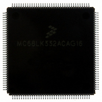
MC68LK332ACAG16 Freescale Semiconductor, MC68LK332ACAG16 Datasheet - Page 25

MC68LK332ACAG16
Manufacturer Part Number
MC68LK332ACAG16
Description
IC MCU 32BIT LV AMASK 144-LQFP
Manufacturer
Freescale Semiconductor
Series
M683xxr
Specifications of MC68LK332ACAG16
Core Processor
CPU32
Core Size
32-Bit
Speed
16.78MHz
Connectivity
EBI/EMI, SCI, SPI, UART/USART
Peripherals
POR, PWM, WDT
Number Of I /o
15
Program Memory Type
ROMless
Ram Size
2K x 8
Voltage - Supply (vcc/vdd)
3 V ~ 3.6 V
Oscillator Type
Internal
Operating Temperature
-40°C ~ 85°C
Package / Case
144-LQFP
Processor Series
M683xx
Core
CPU32
Data Bus Width
32 bit
Maximum Clock Frequency
16 MHz
Maximum Operating Temperature
+ 85 C
Mounting Style
SMD/SMT
Interface Type
QSPI, SCI, UART
Minimum Operating Temperature
- 40 C
No. Of I/o's
15
Ram Memory Size
2KB
Cpu Speed
16MHz
No. Of Timers
16
Embedded Interface Type
QSPI, SCI, UART
Digital Ic Case Style
LQFP
Rohs Compliant
Yes
Data Ram Size
2 KB
Number Of Programmable I/os
15
Number Of Timers
16
Cpu Family
68K/M683xx
Device Core
ColdFire
Device Core Size
32b
Frequency (max)
16MHz
Program Memory Size
Not Required
Total Internal Ram Size
2KB
# I/os (max)
15
Number Of Timers - General Purpose
16
Operating Supply Voltage (typ)
5V
Instruction Set Architecture
RISC
Operating Temp Range
-40C to 85C
Operating Temperature Classification
Industrial
Mounting
Surface Mount
Pin Count
144
Package Type
LQFP
Lead Free Status / RoHS Status
Lead free / RoHS Compliant
Eeprom Size
-
Program Memory Size
-
Data Converters
-
Lead Free Status / Rohs Status
Lead free / RoHS Compliant
Available stocks
Company
Part Number
Manufacturer
Quantity
Price
Company:
Part Number:
MC68LK332ACAG16
Manufacturer:
MOTOLOLA
Quantity:
1 045
Company:
Part Number:
MC68LK332ACAG16
Manufacturer:
Freescale Semiconductor
Quantity:
10 000
Part Number:
MC68LK332ACAG16
Manufacturer:
FREESCALE
Quantity:
20 000
3.3.3 Clock Control
SYNCR —Clock Synthesizer Control Register
W — Frequency Control (VCO)
X — Frequency Control Bit (Prescale)
Y[5:0] — Frequency Control (Counter)
EDIV — E Clock Divide Rate
SLIMP — Limp Mode Flag
SLOCK — Synthesizer Lock Flag
RSTEN — Reset Enable
STSIM — Stop Mode SIM Clock
STEXT — Stop Mode External Clock
MC68332
MC68332TS/D
RESET:
15
W
0
The clock control circuits determine system clock frequency and clock operation under special circum-
stances, such as following loss of synthesizer reference or during low-power operation. Clock source is
determined by the logic state of the MODCLK pin during reset.
When the on-chip clock synthesizer is used, system clock frequency is controlled by the bits in the upper
byte of SYNCR. Bits in the lower byte show status of or control operation of internal and external clocks.
The SYNCR can be read or written only when the CPU is operating at the supervisor privilege level.
This bit controls a prescaler tap in the synthesizer feedback loop. Setting the bit increases the VCO
speed by a factor of four. VCO relock delay is required.
This bit controls a divide by two prescaler that is not in the synthesizer feedback loop. Setting the bit
doubles clock speed without changing the VCO speed. There is no VCO relock delay.
The Y field controls the modulus down counter in the synthesizer feedback loop, causing it to divide by
a value of Y
ECLK is an external M6800 bus clock available on pin ADDR23. Refer to 3.5 Chip Selects for more
information.
When the on-chip synthesizer is used, loss of reference frequency causes SLIMP to be set. The VCO
continues to run using the base control voltage. Maximum limp frequency is maximum specified system
clock frequency. X-bit state affects limp frequency.
The MCU maintains reset state until the synthesizer locks, but SLOCK does not indicate synthesizer
lock status until after the user writes to SYNCR.
0 = ECLK frequency is system clock divided by 8.
1 = ECLK frequency is system clock divided by 16.
0 = External crystal is VCO reference.
1 = Loss of crystal reference.
0 = VCO is enabled, but has not locked.
1 = VCO has locked on the desired frequency (or system clock is external).
0 = Loss of crystal causes the MCU to operate in limp mode.
1 = Loss of crystal causes system reset.
0 = When LPSTOP is executed, the SIM clock is driven from the crystal oscillator and the VCO is
1 = When LPSTOP is executed, the SIM clock is driven from the VCO.
0 = When LPSTOP is executed, the CLKOUT signal is held negated to conserve power.
1 = When LPSTOP is executed, the CLKOUT signal is driven from the SIM clock, as determined by
14
X
0
turned off to conserve power.
the state of the STSIM bit.
13
1
1. Values range from 0 to 63. VCO relock delay is required.
1
Freescale Semiconductor, Inc.
For More Information On This Product,
1
Y
1
Go to: www.freescale.com
1
8
1
EDIV
7
0
6
0
0
5
0
0
SLIMP SLOCK RSTEN STSIM STEXT
U
4
U
3
2
0
MOTOROLA
$YFFA04
1
0
0
0
25


