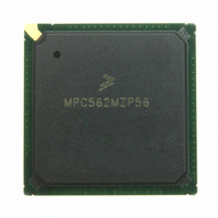
MPC562MZP56 Freescale Semiconductor, MPC562MZP56 Datasheet - Page 924

MPC562MZP56
Manufacturer Part Number
MPC562MZP56
Description
IC MPU 32BIT 56MHZ PPC 388-PBGA
Manufacturer
Freescale Semiconductor
Series
MPC5xxr
Datasheet
1.MPC561MZP56.pdf
(1420 pages)
Specifications of MPC562MZP56
Core Processor
PowerPC
Core Size
32-Bit
Speed
56MHz
Connectivity
CAN, EBI/EMI, SCI, SPI, UART/USART
Peripherals
POR, PWM, WDT
Number Of I /o
64
Program Memory Type
ROMless
Ram Size
32K x 8
Voltage - Supply (vcc/vdd)
2.5 V ~ 2.7 V
Data Converters
A/D 32x10b
Oscillator Type
External
Operating Temperature
-40°C ~ 125°C
Package / Case
388-BGA
Processor Series
MPC5xx
Core
PowerPC
Data Bus Width
32 bit
Data Ram Size
8 KB
Interface Type
SCI, SPI, UART
Maximum Clock Frequency
40 MHz
Number Of Programmable I/os
56
Number Of Timers
22
Operating Supply Voltage
2.6 V to 5 V
Maximum Operating Temperature
+ 85 C
Mounting Style
SMD/SMT
Minimum Operating Temperature
- 40 C
On-chip Adc
2 (10 bit, 32 Channel)
For Use With
MPC564EVB - KIT EVAL FOR MPC561/562/563/564
Lead Free Status / RoHS Status
Request inventory verification / Request inventory verification
Eeprom Size
-
Program Memory Size
-
Lead Free Status / Rohs Status
No
Available stocks
Company
Part Number
Manufacturer
Quantity
Price
Company:
Part Number:
MPC562MZP56
Manufacturer:
FREESCAL
Quantity:
204
Company:
Part Number:
MPC562MZP56
Manufacturer:
Freescale Semiconductor
Quantity:
10 000
Part Number:
MPC562MZP56
Manufacturer:
FREESCALE
Quantity:
20 000
Company:
Part Number:
MPC562MZP56R2
Manufacturer:
RFT
Quantity:
1 441
Company:
Part Number:
MPC562MZP56R2
Manufacturer:
Freescale Semiconductor
Quantity:
10 000
- Current page: 924 of 1420
- Download datasheet (11Mb)
Development Support
The comparators generate match events. The match events enter the instruction AND-OR logic where the
instruction watchpoints and breakpoint are generated. The instruction watchpoints, when asserted, may
generate the instruction breakpoint. Two of them may decrement one of the counters. If one of the
instruction watchpoints expires in a counter that is counting, the instruction breakpoint is asserted.
The instruction watchpoints and the load/store match events (address and data) enter the load/store
AND-OR logic where the load/store watchpoints and breakpoint are generated. The load/store
watchpoints, when asserted, may generate the load/store breakpoint or they may decrement one of the
counters. When a counter that is counting one of the load/store watchpoints expires, the load/store
breakpoint is asserted.
Watchpoints progress in the machine and are reported on retirement. Internal breakpoints progress in the
machine until they reach the top of the history buffer when the machine branches to the breakpoint
exception routine.
In order to enable the use of the breakpoint features without adding restrictions on the software, the address
of the load/store cycle that generated the load/store breakpoint is not stored in the DAR (data address
register), like other load/store type exceptions. In case of a load/store breakpoint, the address of the
load/store cycle that generated the breakpoint is stored in an implementation-dependent register called the
BAR (breakpoint address register).
Key features of internal watchpoint and breakpoint support are:
23-10
•
•
•
•
•
•
•
•
•
•
Four I-address comparators (each supports equal, not equal, greater than, less than)
Two L-address comparators (each supports equal, not equal, greater than, less than) including least
significant bits masking according to the size of the bus cycle for the byte and half-word working
modes. Refer to
Two L-data comparators (each supports equal, not equal, greater than, less than) including byte,
half-word and word operating modes and four byte mask bits for each comparator. Can be used for
fix point data. Match is detected only on the valid part of the data bus (according to the cycle’s size
and the two address least significant bits).
No internal breakpoint/watchpoint matching support for unaligned words and half-words
The L-data comparators can be programmed to treat fix point numbers as signed values or as
unsigned values
Combine comparator pairs to detect in and out of range conditions (including either signed or
unsigned values on the L-data)
A programmable AND-OR logic structure between the four instruction comparators results with
five outputs, four instruction watchpoints and one instruction breakpoint
A programmable AND-OR logic structure between the four instruction watchpoints and the four
load/store comparators results with three outputs, two load/store watchpoints and one load/store
breakpoint
Five watchpoint pins, three for the instruction and two for the load/store
Two dedicated 16-bit down counters. Each can be programmed to count either an instruction
watchpoint or an load/store watchpoint. Only architecturally executed events are counted, (count
up is performed in case of recovery).
Section 23.2.1.2, “Byte and Half-Word Working
MPC561/MPC563 Reference Manual, Rev. 1.2
Modes.”
Freescale Semiconductor
Related parts for MPC562MZP56
Image
Part Number
Description
Manufacturer
Datasheet
Request
R
Part Number:
Description:
Mpc562 32 Bit Powerpc Microcontroller
Manufacturer:
Freescale Semiconductor, Inc
Datasheet:

Part Number:
Description:
MPC5 1K0 5%
Manufacturer:
TE Connectivity
Datasheet:

Part Number:
Description:
MPC5 500R 5%
Manufacturer:
TE Connectivity
Datasheet:

Part Number:
Description:
MPC5 5K0 5%
Manufacturer:
Tyco Electronics
Datasheet:

Part Number:
Description:
MPC5 5R0 5%
Manufacturer:
Tyco Electronics
Datasheet:

Part Number:
Description:
MPC5 50K 5%
Manufacturer:
Tyco Electronics
Datasheet:
Part Number:
Description:
Manufacturer:
Freescale Semiconductor, Inc
Datasheet:
Part Number:
Description:
Manufacturer:
Freescale Semiconductor, Inc
Datasheet:
Part Number:
Description:
Manufacturer:
Freescale Semiconductor, Inc
Datasheet:
Part Number:
Description:
Manufacturer:
Freescale Semiconductor, Inc
Datasheet:
Part Number:
Description:
Manufacturer:
Freescale Semiconductor, Inc
Datasheet:


