PIC16C56A/JW Microchip Technology, PIC16C56A/JW Datasheet - Page 23
PIC16C56A/JW
Manufacturer Part Number
PIC16C56A/JW
Description
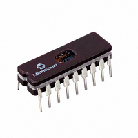
IC MCU EPROM 1KX12 18CDIP
Manufacturer
Microchip Technology
Series
PIC® 16Cr
Specifications of PIC16C56A/JW
Core Processor
PIC
Core Size
8-Bit
Speed
20MHz
Peripherals
POR, WDT
Number Of I /o
12
Program Memory Size
1.5KB (1K x 12)
Program Memory Type
EPROM, UV
Ram Size
25 x 8
Voltage - Supply (vcc/vdd)
3 V ~ 5.5 V
Oscillator Type
External
Operating Temperature
0°C ~ 70°C
Package / Case
18-CDIP (0.300", 7.62mm) Window
Lead Free Status / RoHS Status
Contains lead / RoHS non-compliant
Eeprom Size
-
Data Converters
-
Connectivity
-
Available stocks
Company
Part Number
Manufacturer
Quantity
Price
Company:

Part Number:
PIC16C56A/JW
Manufacturer:
Microchip Technology
Quantity:
2


5.1
The PIC16C5X family incorporates on-chip Power-On
Reset (POR) circuitry which provides an internal chip
RESET for most power-up situations. To use this fea-
ture, the user merely ties the MCLR/V
simplified block diagram of the on-chip Power-On
Reset circuit is shown in Figure 5-1.
The Power-On Reset circuit and the Device Reset
Timer (Section 5.2) circuit are closely related. On
power-up, the RESET latch is set and the DRT is
RESET. The DRT timer begins counting once it detects
MCLR to be high. After the time-out period, which is
typically 18 ms, it will RESET the reset latch and thus
end the on-chip RESET signal.
A power-up example where MCLR is not tied to V
shown in Figure 5-3. V
before bringing MCLR high. The chip will actually come
out of reset T
In Figure 5-4, the on-chip Power-On Reset feature is
being used (MCLR and V
is stable before the start-up timer times out and there is
no problem in getting a proper RESET. However,
Figure 5-5 depicts a problem situation where V
too slowly. The time between when the DRT senses a
high on the MCLR/V
pin (and V
In this situation, when the start-up timer times out, V
has not reached the V
therefore, not guaranteed to function correctly. For
such situations, we recommend that external RC cir-
cuits be used to achieve longer POR delay times
(Figure 5-2).
For more information on PIC16C5X POR, see Power-
Up Considerations - AN522 in the Embedded Control
Handbook.
The POR circuit does not produce an internal RESET
when V
Note:
2002 Microchip Technology Inc.
DD
Power-On Reset (POR)
DD
declines.
When the device starts normal operation
(exits the RESET condition), device oper-
ating parameters (voltage, frequency, tem-
perature, etc.) must be met to ensure
operation. If these conditions are not met,
the device must be held in RESET until the
operating conditions are met.
) actually reach their full value, is too long.
DRT
msec after MCLR goes high.
PP
DD
DD
pin, and when the MCLR/V
DD
is allowed to rise and stabilize
(min) value and the chip is,
are tied together). The V
PP
pin to V
DD
DD
DD
rises
Preliminary
. A
DD
DD
PP
is
FIGURE 5-2:
• External Power-On Reset circuit is required
• R < 40 k is recommended to make sure that
• R1 = 100
only if V
helps discharge the capacitor quickly when
V
voltage drop across R does not violate the
device electrical specification.
ing into MCLR from external capacitor C in the
event of MCLR pin breakdown due to Electro-
static Discharge (ESD) or Electrical Over-
stress (EOS).
DD
V
DD
powers down.
D
DD
V
power-up is too slow. The diode D
to 1 k will limit any current flow-
DD
R
EXTERNAL POWER-ON
RESET CIRCUIT (FOR
SLOW VDD POWER-UP)
C
R1
PIC16C5X
MCLR
DS30453D-page 21
PIC16C5X
Related parts for PIC16C56A/JW
Image
Part Number
Description
Manufacturer
Datasheet
Request
R

Part Number:
Description:
Manufacturer:
Microchip Technology Inc.
Datasheet:

Part Number:
Description:
IC MCU OTP 1KX12 18SOIC
Manufacturer:
Microchip Technology
Datasheet:

Part Number:
Description:
IC MCU OTP 1KX12 18DIP
Manufacturer:
Microchip Technology
Datasheet:
Part Number:
Description:
IC MCU OTP 1KX12 18DIP
Manufacturer:
Microchip Technology
Datasheet:
Part Number:
Description:
IC MCU OTP 1KX12 18DIP
Manufacturer:
Microchip Technology
Datasheet:
Part Number:
Description:
IC MCU OTP 1KX12 18DIP
Manufacturer:
Microchip Technology
Datasheet:
Part Number:
Description:
IC MCU OTP 1KX12 18SOIC
Manufacturer:
Microchip Technology
Datasheet:
Part Number:
Description:
IC MCU OTP 1KX12 18DIP
Manufacturer:
Microchip Technology
Datasheet:
Part Number:
Description:
IC MCU OTP 1KX12 18SOIC
Manufacturer:
Microchip Technology
Datasheet:

Part Number:
Description:
IC MCU OTP 1KX12 20SSOP
Manufacturer:
Microchip Technology
Datasheet:
Part Number:
Description:
IC MCU OTP 1KX12 20SSOP
Manufacturer:
Microchip Technology
Datasheet:
Part Number:
Description:
IC MCU OTP 1KX12 18SOIC
Manufacturer:
Microchip Technology
Datasheet:
Part Number:
Description:
IC MCU OTP 1KX12 18DIP
Manufacturer:
Microchip Technology
Datasheet:
Part Number:
Description:
IC MCU OTP 1KX12 18DIP
Manufacturer:
Microchip Technology
Datasheet:
Part Number:
Description:
IC MCU OTP 1KX12 18DIP
Manufacturer:
Microchip Technology
Datasheet: