PIC16C56A/JW Microchip Technology, PIC16C56A/JW Datasheet - Page 34
PIC16C56A/JW
Manufacturer Part Number
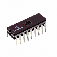
PIC16C56A/JW
Description
IC MCU EPROM 1KX12 18CDIP
Manufacturer
Microchip Technology
Series
PIC® 16Cr
Specifications of PIC16C56A/JW
Core Processor
PIC
Core Size
8-Bit
Speed
20MHz
Peripherals
POR, WDT
Number Of I /o
12
Program Memory Size
1.5KB (1K x 12)
Program Memory Type
EPROM, UV
Ram Size
25 x 8
Voltage - Supply (vcc/vdd)
3 V ~ 5.5 V
Oscillator Type
External
Operating Temperature
0°C ~ 70°C
Package / Case
18-CDIP (0.300", 7.62mm) Window
Lead Free Status / RoHS Status
Contains lead / RoHS non-compliant
Eeprom Size
-
Data Converters
-
Connectivity
-
Available stocks
Company
Part Number
Manufacturer
Quantity
Price
Company:

Part Number:
PIC16C56A/JW
Manufacturer:
Microchip Technology
Quantity:
2


PIC16C5X
6.5.1
If the Program Counter is pointing to the last address of
a selected memory page, when it increments it will
cause the program to continue in the next higher page.
However, the page preselect bits in the STATUS Reg-
ister will not be updated. Therefore, the next GOTO,
CALL or modify PCL instruction will send the program
to the page specified by the page preselect bits (PA0 or
PA<1:0>).
For example, a NOP at location 1FFh (page 0) incre-
ments the PC to 200h (page 1). A GOTO xxx at 200h
will return the program to address xxh on page 0
(assuming that PA<1:0> are clear).
To prevent this, the page preselect bits must be
updated under program control.
6.5.2
The Program Counter is set upon a RESET, which
means that the PC addresses the last location in the
last page (i.e., the RESET vector).
The STATUS Register page preselect bits are cleared
upon a RESET, which means that page 0 is pre-
selected.
Therefore, upon a RESET, a GOTO instruction at the
RESET vector location will automatically cause the pro-
gram to jump to page 0.
6.6
PIC16C5X devices have a 10-bit or 11-bit wide, two-
level hardware push/pop stack.
A CALL instruction will push the current value of stack
1 into stack 2 and then push the current program
counter value, incremented by one, into stack level 1. If
more than two sequential CALL’s are executed, only
the most recent two return addresses are stored.
A RETLW instruction will pop the contents of stack level
1 into the program counter and then copy stack level 2
contents into level 1. If more than two sequential
RETLW’s are executed, the stack will be filled with the
address previously stored in level 2. Note that the
W Register will be loaded with the literal value specified
in the instruction. This is particularly useful for the
implementation of data look-up tables within the pro-
gram memory.
For the RETLW instruction, the PC is loaded with the
Top of Stack (TOS) contents. All of the devices covered
in this data sheet have a two-level stack. The stack has
the same bit width as the device PC, therefore, paging
is not an issue when returning from a subroutine.
DS30453D-page 32
Stack
PAGING CONSIDERATIONS –
PIC16C56/CR56, PIC16C57/CR57
AND PIC16C58/CR58
EFFECTS OF RESET
Preliminary
2002 Microchip Technology Inc.
Related parts for PIC16C56A/JW
Image
Part Number
Description
Manufacturer
Datasheet
Request
R

Part Number:
Description:
Manufacturer:
Microchip Technology Inc.
Datasheet:

Part Number:
Description:
IC MCU OTP 1KX12 18SOIC
Manufacturer:
Microchip Technology
Datasheet:

Part Number:
Description:
IC MCU OTP 1KX12 18DIP
Manufacturer:
Microchip Technology
Datasheet:
Part Number:
Description:
IC MCU OTP 1KX12 18DIP
Manufacturer:
Microchip Technology
Datasheet:
Part Number:
Description:
IC MCU OTP 1KX12 18DIP
Manufacturer:
Microchip Technology
Datasheet:
Part Number:
Description:
IC MCU OTP 1KX12 18DIP
Manufacturer:
Microchip Technology
Datasheet:
Part Number:
Description:
IC MCU OTP 1KX12 18SOIC
Manufacturer:
Microchip Technology
Datasheet:
Part Number:
Description:
IC MCU OTP 1KX12 18DIP
Manufacturer:
Microchip Technology
Datasheet:
Part Number:
Description:
IC MCU OTP 1KX12 18SOIC
Manufacturer:
Microchip Technology
Datasheet:

Part Number:
Description:
IC MCU OTP 1KX12 20SSOP
Manufacturer:
Microchip Technology
Datasheet:
Part Number:
Description:
IC MCU OTP 1KX12 20SSOP
Manufacturer:
Microchip Technology
Datasheet:
Part Number:
Description:
IC MCU OTP 1KX12 18SOIC
Manufacturer:
Microchip Technology
Datasheet:
Part Number:
Description:
IC MCU OTP 1KX12 18DIP
Manufacturer:
Microchip Technology
Datasheet:
Part Number:
Description:
IC MCU OTP 1KX12 18DIP
Manufacturer:
Microchip Technology
Datasheet:
Part Number:
Description:
IC MCU OTP 1KX12 18DIP
Manufacturer:
Microchip Technology
Datasheet: