LMH2100TM/NOPB National Semiconductor, LMH2100TM/NOPB Datasheet - Page 5
LMH2100TM/NOPB
Manufacturer Part Number
LMH2100TM/NOPB
Description
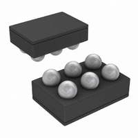
IC LOG DETECTOR 4GHZ 40DB 6MSMD
Manufacturer
National Semiconductor
Datasheet
1.LMH2100TMNOPB.pdf
(32 pages)
Specifications of LMH2100TM/NOPB
Frequency
50MHz ~ 4GHz
Rf Type
Cellular, W-CDMA, CDMA, GSM, UMTS
Input Range
-45dBm ~ -5dBm
Accuracy
0.5dB
Voltage - Supply
2.7 V ~ 3.3 V
Current - Supply
9.2mA
Package / Case
6-UFBGA
Pin Count
6
Screening Level
Industrial
Lead Free Status / RoHS Status
Lead free / RoHS Compliant
Other names
LMH2100TMTR


S
S
P
P
DR
Symbol
T
T
MAX
MIN
Note 1: Absolute Maximum Ratings indicate limits beyond which damage to the device may occur. Operating Ratings indicate conditions for which the device is
intended to be functional, but specific performance is not guaranteed. For guaranteed specifications and the test conditions, see the Electrical Characteristics.
Note 2: Human body model, applicable std. MIL-STD-883, Method 3015.7. Machine model, applicable std. JESD22–A115–A (ESD MM std of JEDEC). Field-
Induced Charge-Device Model, applicable std. JESD22–C101–C. (ESD FICDM std. of JEDEC)
Note 3: The maximum power dissipation is a function of T
P
Note 4: Electrical Table values apply only for factory testing conditions at the temperature indicated. Factory testing conditions result in very limited self-heating
of the device such that T
T
Note 5: Power in dBV = dBm + 13 when the impedance is 50Ω.
Note 6: All limits are guaranteed by test or statistical analysis.
Note 7: Typical values represent the most likely parametric norm as determined at the time of characterization. Actual typical values may vary over time and will
also depend on the application and configuration. The typical values are not tested and are not guaranteed on shipped production material.
Note 8: All limits are guaranteed by design and measurements which are performed on a limited number of samples. Limits represent the mean ±3–sigma values.
The typical value represents the statistical mean value.
Note 9: This parameter is guaranteed by design and/or characterization and is not tested in production.
D
J
> T
= (T
A
.
J(MAX)
Temperature Sensitivity
−40°C < T
P
Temperature Sensitivity
25°C < T
P
Maximum Input Power for
E
Minimum Input Power for
E
Dynamic Range for E
(Note 8)
- T
IN
IN
LC
LC
A
= −10 dBm
= −10 dBm
)/θ
= 1 dB(Note 8)
= 1 dB (Note 8)
JA
. All numbers apply for packages soldered directly into a PC board.
A
J
A
< 85°C, (Note 8)
Parameter
= T
< 25°C, (Note 8)
A
. No guarantee of parametric performance is indicated in the electrical tables under conditions of internal self-heating where
LC
= 1 dB
f = 50 MHz
f = 900 MHz
f = 1855 MHz
f = 2500 MHz
f = 3000 MHz
f = 3500 MHz
f = 4000 MHz
f = 50 MHz
f = 900 MHz
f = 1855 MHz
f = 2500 MHz
f = 3000 MHz
f = 3500 MHz
f = 4000 MHz
f = 50 MHz
f = 900 MHz
f = 1855 MHz
f = 2500 MHz
f = 3000 MHz
f = 3500 MHz
f = 4000 MHz
f = 50 MHz
f = 900 MHz
f = 1855 MHz
f = 2500 MHz
f = 3000 MHz
f = 3500 MHz
f = 4000 MHz
f = 50 MHz
f = 900 MHz
f = 1855 MHz
f = 2500 MHz
f = 3000 MHz
f = 3500 MHz
f = 4000 MHz
J(MAX)
, θ
JA
. The maximum allowable power dissipation at any ambient temperature is
Condition
5
(Note 6)
-10.5
-10.5
-11.3
-10.6
-11.2
-12.9
-17.8
-10.5
-11.1
29.5
33.3
34.2
34.1
33.4
28.5
22.7
Min
-5.4
-3.1
-1.6
-9.2
-8.2
-7.3
-6.3
-6.9
0.3
0.9
2.5
2.7
(Note 7)
-38.9
-43.1
-42.2
-40.6
-38.7
-35.9
-33.5
31.6
35.2
36.5
36.1
35.5
35.1
26.3
Typ
-7.4
-8.6
-6.5
-5.6
-4.4
-1.9
-7.2
(Note 6)
-38.1
-42.3
-41.0
-38.9
-37.0
-34.7
-32.0
Max
14.5
11.0
13.6
15.8
16.9
17.3
-1.1
8.6
0.5
2.6
3.3
5.4
6.1
4.4
www.national.com
mdB/°C
mdB/°C
Units
dBm
dBm
dB
Related parts for LMH2100TM/NOPB
Image
Part Number
Description
Manufacturer
Datasheet
Request
R

Part Number:
Description:
50 MHz to 4 GHz 40 dB Logarithmic Power Detector for CDMA and Wcdma
Manufacturer:
National Semiconductor Corporation
Datasheet:

Part Number:
Description:
National Semiconductor [8-Bit D/A Converter]
Manufacturer:
National Semiconductor
Datasheet:
Part Number:
Description:
National Semiconductor [Media Coprocessor]
Manufacturer:
National Semiconductor
Datasheet:
Part Number:
Description:
Digitally Controlled Tone and Volume Circuit with Stereo Audio Power Amplifier, Microphone Preamp Stage and National 3D Sound
Manufacturer:
National Semiconductor
Datasheet:
Part Number:
Description:
Digitally Controlled Tone and Volume Circuit with Stereo Audio Power Amplifier, Microphone Preamp Stage and National 3D Sound
Manufacturer:
National Semiconductor
Datasheet:
Part Number:
Description:
AC97 Rev 2 Codec with Sample Rate Conversion and National 3D Sound
Manufacturer:
National Semiconductor
Part Number:
Description:
Manufacturer:
National Semiconductor
Datasheet:
Part Number:
Description:
Manufacturer:
National Semiconductor
Datasheet:
Part Number:
Description:
General Purpose, Low Voltage, Low Power, Rail-to-Rail Output Operational Amplifiers
Manufacturer:
National Semiconductor
Datasheet:
Part Number:
Description:
8-bit 20 MSPS flash A/D converter.
Manufacturer:
National Semiconductor
Datasheet:
Part Number:
Description:
Low Noise Quad Operational Amplifier
Manufacturer:
National Semiconductor
Datasheet:
Part Number:
Description:
Quad Differential Line Receivers
Manufacturer:
National Semiconductor
Datasheet:
Part Number:
Description:
Quad High Speed Trapezoidal? Bus Transceiver
Manufacturer:
National Semiconductor
Datasheet:
Part Number:
Description:
Dual Line Receiver
Manufacturer:
National Semiconductor
Datasheet: