E3JM-R4M4-G Omron, E3JM-R4M4-G Datasheet - Page 7
E3JM-R4M4-G
Manufacturer Part Number
E3JM-R4M4-G
Description
Industrial Photoelectric Sensors PES W/PG13.5 CONDUIT ENTRY
Manufacturer
Omron
Specifications of E3JM-R4M4-G
Output
Relay
Sensing Method
Polarized Retroreflective
Sensing Distance
4 m (13.1 ft)
Light Source
Infrared LED
Connection
Screw Terminals
Output Configuration
Relay
Svhc
No SVHC (15-Dec-2010)
Sensing Range Max
4m
Sensor Input
Optical
Supply Voltage Ac Max
240V
Supply Voltage Dc Max
240V
Connector Type
Screw Terminal
Contact Configuration
SPDT 3A 230VAC(max.),
Output Type
SPDT
Rohs Compliant
Yes
Sensing Range
4m
Sensor Output
SPDT-Relay
Lead Free Status / RoHS Status
Lead free / RoHS Compliant
Lead Free Status / RoHS Status
Lead free / RoHS Compliant, Lead free / RoHS Compliant
Available stocks
Company
Part Number
Manufacturer
Quantity
Price
Company:

Part Number:
E3JM-R4M4-G
Manufacturer:
SHARP
Quantity:
4 890


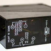
Switch Selection
Connecting and Wiring
Recommended outer diameter of cables is from 6 to 8 dia.
Be sure to firmly tighten the cover in order to maintain waterproof
and dustproof properties.
Cable End Treatment
Adjust the four wires to the same length when the Ta output is to
be used only. If both the Ta and Tb outputs are to be used, treat
them as shown in the following diagram.
Recommended Crimp Terminal Dimensions
(Unit: mm)
Note: Use terminals with insulation tube (recommended crimp terminal: 1.25
E3JM
Models without Timer
D·ON
D·ON
to 3.5).
Approx. 45 mm
Approx. 55 mm
MODE
MODE
0
0
1
1
L·ON
L·ON
7 max.
7 max.
3.6 dia. min.
3.6 dia. min.
Power
source
Tc, Ta
Dark-ON, Transistor output ON
Light-ON, Transistor output ON
(After crimping)
(After crimping)
Round type
Fork type
10 max.
Tightening nut (accessory) (See note.)
19 max.
19 max.
10 max.
Washer (accessory) (See note.)
Rubber bushing
(accessory) (See note.)
7 max.
7 max.
Models with Timer
Both SW1 and SW2 at "0."
TIMER
Note: The switch for the operating mode is the same as that for
D·ON
ON-delay
Terminal Protection Cover (Accessory)
The terminal protection cover is designed to improve safety by
maintaining the sensitivity properties of the product and by pre-
venting any contact with charged sections while it is being oper-
ated with the mode set to the timer mode. Mount the product as
shown in the following diagram (mount the Through-beam Model
on the Receiver side).
Output Relay Contact
If a load, such as contactor or valve is used that may produce arc
when it is turned OFF, the NC (or NO) side may turn ON before
the NO (or NC) side is turned OFF. When using both the NC and
NO outputs, use an arc killer.
Connecting and Wiring DC SSR Output Models
When using the DC SSR output model, the total of the load cur-
rent for the Light-ON output (NO) and that for the Dark-ON (NC)
should be 100 mA max. If the total exceeds 100 mA, the load
short-circuit protection function will be activated (this function will
be reset when the power of the Photoelectric Sensor is turned
OFF ).
MODE
0
models without a timer.
1
L·ON
SW1
SW2
TIMER
D·ON
Only SW2 at "1."
OFF-delay
MODE
0
1
L·ON
SW1
SW2
TIMER
Only SW1 at "1,"
which overrides either
setting of SW2.
One-shot delay
D·ON
MODE
0
Terminal protection cover
E3JM
1
L·ON
SW1
SW2
7
Related parts for E3JM-R4M4-G
Image
Part Number
Description
Manufacturer
Datasheet
Request
R

Part Number:
Description:
Photoelectric Sensors - Industrial E3JM Emitter only
Manufacturer:
Omron
Part Number:
Description:
Photoelectric Sensors - Industrial EMITTER FOR E3JM-10M 4(T)-US
Manufacturer:
Omron

Part Number:
Description:
G6S-2GLow Signal Relay
Manufacturer:
Omron Corporation
Datasheet:
Part Number:
Description:
Compact, Low-cost, SSR Switching 5 to 20 A
Manufacturer:
Omron Corporation
Datasheet:
Part Number:
Description:
Manufacturer:
Omron Corporation
Datasheet: