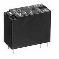
JW2ASN-DC12V Panasonic, JW2ASN-DC12V Datasheet - Page 4

JW2ASN-DC12V
Manufacturer Part Number
JW2ASN-DC12V
Description
General Purpose / Industrial Relays 5A 12VDC DPST-NO NON-LATCHING PCB
Manufacturer
Panasonic
Datasheet
1.JW1FSN-DC5V.pdf
(7 pages)
Specifications of JW2ASN-DC12V
Contact Form
2 Form A
Coil Voltage
12 VDC
Contact Rating
5 A at 250 VAC, 5 A at 30 VDC
Coil Termination
Solder Pin
Contact Termination
Solder Pin
Mounting Style
Through Hole
Power Consumption
530 mW
Contact Material
Silver Tin Oxide
Coil Current
44 mA
Coil Resistance
270 Ohms
Coil Type
Standard
Lead Free Status / RoHS Status
Lead free / RoHS Compliant
Available stocks
Company
Part Number
Manufacturer
Quantity
Price
JW
JW 1 Form A High Capacity (10 A) type
1. Maximum operating power
4-(1). Coil temperature rise
(Contact carrying current: 5A)
Sample JW1aFSN-DC12V-F, 6 pcs.
Point measured: Inside the coil
JW 1 Form C Standard (5 A) type
1-(3). Maximum operating power
JW 2 Form A Standard (5 A) type
1. Maximum operating power
100
70
60
50
40
30
20
10
10
10
10
0
1
0
1
1
0
AC resistive load (cos = 1.0)
AC resistive load (cos = 1.0)
100
DC resistive
load
10
10
10
Coil applied voltage, %V
120
Contact voltage, V
Contact voltage, V
Contact voltage, V
AC resistive
load
100
100
100
140
25 C
60 C
85 C
1,000
1,000
1,000
160
All Rights Reserved © COPYRIGHT Panasonic Electric Works Co., Ltd.
2. Operate/release time
Sample: JW1aFSN-DC12V, 10 pcs.
Ambient temperature: 20 C
4-(2). Coil temperature rise
(Contact carrying current: 10 A)
Sample: JW1aFSN-DC12V-F, 6 pcs.
Point measured: Inside the coil
2. Operate/release time
Sample: JW1SN-DC12V-F, 6 pcs.
Ambient temperature: 20 C
2. Operate/release time
Sample: JW2aSN-DC24V-F, 6 pcs.
Ambient temperature: 20 C
70
60
50
40
30
20
10
10
13
12
11
10
14
14
13
13
12
12
10
10
5
0
0
9
8
7
6
5
4
3
2 2
1
8
8
6
6
4
4
2
2
80
80
80
80
100
80
90
90
90
90
Release time
90
Coil applied voltage, %V
Coil applied voltage, %V
Coil applied voltage, %V
Coil applied voltage, %V
100
120
Release time
Operate time
100
100
100
Operate time
68 F
68 F
68 F
110
110
110
110
110
140
120
120
120
Max.
x -
Min.
Max.
x -
Min.
120
120
25 C
60 C
85 C
130
Max.
x -
Min.
Max.
x -
Min.
Max.
Min.
Max.
Max.
Min.
Min.
x -
x -
160
3. Life curve
JW 1 Form C High Capacity (10 A) type
1. Maximum operating power
100
10
10
1
1
0
0
AC resistive load (cos = 1.0)
2
10
4
250 V AC resistive load
Contact current, A
30 V DC resistive load
Contact voltage, V
6
100
8
10
1,000
12


