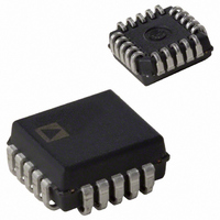
AD831AP Analog Devices Inc, AD831AP Datasheet - Page 10

AD831AP
Manufacturer Part Number
AD831AP
Description
LOW DISTORTION 500 MHZ MIXER IC
Manufacturer
Analog Devices Inc
Series
AD831r
Datasheet
1.AD831APZ.pdf
(16 pages)
Specifications of AD831AP
Peak Reflow Compatible (260 C)
No
Leaded Process Compatible
No
Rohs Status
RoHS non-compliant
Rf Type
HF, VHF
Frequency
500MHz
Number Of Mixers
1
Gain
0dB
Noise Figure
14dB
Secondary Attributes
Down Converter
Current - Supply
125mA
Voltage - Supply
4.5 V ~ 5.5 V
Package / Case
20-LCC (J-Lead)
Operating Temperature (min)
-40C
Operating Temperature (max)
85C
Operating Temperature Classification
Industrial
Lead Free Status / RoHS Status
Contains lead / RoHS non-compliant
Lead Free Status / RoHS Status
Contains lead / RoHS non-compliant
Available stocks
Company
Part Number
Manufacturer
Quantity
Price
Part Number:
AD831AP
Manufacturer:
ADI/亚德诺
Quantity:
20 000
Part Number:
AD831AP-REEL
Manufacturer:
ADI/亚德诺
Quantity:
20 000
Part Number:
AD831AP-REEL7
Manufacturer:
ADI/亚德诺
Quantity:
20 000
Company:
Part Number:
AD831AP-REELT
Manufacturer:
VISHAY
Quantity:
1 000
Part Number:
AD831APZ
Manufacturer:
ADI/亚德诺
Quantity:
20 000
Company:
Part Number:
AD831APZ-REEL
Manufacturer:
PHI
Quantity:
2 000
APPLICATIONS
Careful component selection, circuit layout, power supply
dc coupling, and shielding are needed to minimize the AD831’s
susceptibility to interference from radio and TV stations, etc. In
bench evaluation, we recommend placing all of the components
in a shielded box and using feedthrough decoupling networks for
the supply voltage.
Circuit layout and construction are also critical, since stray capaci-
tances and lead inductances can form resonant circuits and are a
potential source of circuit peaking, oscillation, or both.
Dual-Supply Operation
Figure 9 shows the connections for dual-supply operation. Supplies
may be as low as ±4.5 V but should be no higher than ±5.5 V, due
to power dissipation.
AD831
�����
��
Figure 9. Connections for ±5 V Dual-Supply Operation Showing Impedance
Matching Network and Gain of 2 for Driving Reverse-Terminated IF Filter
��
��
��
�����
�����
���
���
���
�
�
�
�
�
�����
���
���
���
��
��
��
�
�
��
���
��������
�������
���
��
�
�����
���
����
�
�
���
–10–
���
��
�
����
��
�
�����
��������
�����
�
The RF input to the AD831 is shown connected by an impedance
matching network for an assumed source impedance of 50 .
TPC 15 shows the input impedance of the AD831 plotted vs.
frequency. The input circuit can be modeled as a resistance in
parallel with a capacitance. The 82 pF capacitors (C
from IFN and IFP to VP provide a low-pass filter with a cutoff
frequency of approximately 140 MHz in down-conversion appli-
cations (see the Theory of Operation section for more details).
The LO input is connected single-ended because the limiting
amplifier provides a symmetric drive to the mixer. To minimize
intermodulation distortion, connect pins OUT and VFB by the
shortest possible path. The connections shown are for unity-gain
operation.
At LO frequencies less than 100 MHz, the AD831’s LO power
may be as low as –20 dBm for satisfactory operation. Above
100 MHz, the specified LO power of –10 dBm must be used.
���
��
��
��
�����
���
���
���
��
��
��
����
���
���
���
��
��
��
��
��
��
�����
����
��
�����
�
�
���
���
�
�
��
������
F
) connected
REV. C


