24140 Cinch Connectors, 24140 Datasheet - Page 156
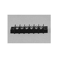
24140
Manufacturer Part Number
24140
Description
Manufacturer
Cinch Connectors
Type
Barrier Stripr
Datasheet
1.24140.pdf
(282 pages)
Specifications of 24140
Number Of Contacts
24POS
Number Of Contact Rows
2
Termination Method
Screw
Mounting Style
Panel
Contact Pitch (mm)
9.53mm
Current Rating (max)
15A
Operating Temp Range
-48C to 148C
Housing Material
Phenolic
Body Orientation
Straight
Operating Voltage (max)
250VAC
Product Height (mm)
28.58mm
Product Length (mm)
245.28mm
Wire Gauge
16
Lead Free Status / RoHS Status
Compliant
Available stocks
Company
Part Number
Manufacturer
Quantity
Price
Company:

Part Number:
241402B91200G
Manufacturer:
ATH
Quantity:
1 020
Company:
Part Number:
241402B92200G
Manufacturer:
ATH
Quantity:
414
Company:
Part Number:
241404B91200G
Manufacturer:
ATH
Quantity:
300
Company:
Part Number:
241404B92200G
Manufacturer:
ATH
Quantity:
262
Company:
Part Number:
241409B91200G
Manufacturer:
ATH
Quantity:
100


D-subminiature Contacts
Coaxial - High Power - High Voltage
Termination Tooling
•
•
NOTE: In order to determine which contact to use with a cable wire not specifically listed:
•
•
•
Call Toll Free: 1 (800) 323-9612
Available in Coaxial (50Ω Ω and 75Ω Ω ), High-Voltage, and High-Power styles.
Cable termination and PCB mount contacts are available in right-angle and straight plugs
and receptacles.
Precision screw machine construction results in uniform contact impedance and excellent
contact retention.
Available with 30µin. or 50µin. gold contact plating.
Cable braid can be soldered or crimped.
See pages 4-55 thru 4-61 for Cinch combination layout D-subminiature connectors.
No tools are required for coaxial contact insertion. Contacts snap into connector. Coaxial and high-voltage contact
extraction tool #CET-C6B for removing contacts after termination. See page 4-103.
Tool to crimp sleeve over cable braid: Use 3-cavity die #CCD-26 with crimp frame #FCT-552. See page 4-103.
Check the style of contact required: straight or right-angle, solder braid or crimp braid, etc.
Refer to the cable wire manufacturer’s specifications to determine:
- The O.D. of the insulator.
- The O.D. of the jacket.
Compare the above with the corresponding dimensions C and E in the straight contacts and dimensions B and
C in the right-angle contacts.
4-62
Related parts for 24140
Image
Part Number
Description
Manufacturer
Datasheet
Request
R

Part Number:
Description:
Standard Card Edge Connectors CINCH BLK CARD GUIDE
Manufacturer:
Cinch Connectors

Part Number:
Description:
TERMINAL BLOCK JUMPER TYPE F
Manufacturer:
Cinch Connectors
Datasheet:
Part Number:
Description:
D-Subminiature Connectors MCHNED PIN 20-24AWG
Manufacturer:
Cinch Connectors
Datasheet:
Part Number:
Description:
Terminal Block,4 Contacts,0.44 Pitch
Manufacturer:
Cinch Connectors
Datasheet:

Part Number:
Description:
Terminal Block,8 Contacts,0.375 Pitch
Manufacturer:
Cinch Connectors
Datasheet: