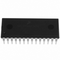
MC3PHACVPE Freescale Semiconductor, MC3PHACVPE Datasheet - Page 14

MC3PHACVPE
Manufacturer Part Number
MC3PHACVPE
Description
IC MOTOR CONTROLLER 28-DIP
Manufacturer
Freescale Semiconductor
Datasheet
1.MC3PHACVFAE.pdf
(36 pages)
Specifications of MC3PHACVPE
Applications
AC Motor Controller, 3 Phase
Number Of Outputs
1
Voltage - Supply
4.5 V ~ 5.5 V
Operating Temperature
-40°C ~ 105°C
Mounting Type
Through Hole
Package / Case
28-DIP (0.600", 15.24mm)
Processor Series
MC3PHAC
Core
HC08
Data Bus Width
8 bit
Program Memory Type
Flash
Program Memory Size
8 KB
Data Ram Size
256 KB
Interface Type
RS-232
Maximum Clock Frequency
21.16 KHz
Number Of Programmable I/os
14
Number Of Timers
1
Operating Supply Voltage
5 V
Maximum Operating Temperature
+ 105 C
Mounting Style
Through Hole
Minimum Operating Temperature
- 40 C
On-chip Adc
10 bit, 4 Channel
Controller Family/series
HC08
Core Size
8 Bit
Ram Memory Size
256Byte
Embedded Interface Type
SCI
Digital Ic Case Style
DIP
No. Of Pins
28
A/d Converter
10 Bits
No. Of Timers 8/12/16/32 Bits
0/0/2/0
Rohs Compliant
Yes
Lead Free Status / RoHS Status
Lead free / RoHS Compliant
Current - Output
-
Voltage - Load
-
Lead Free Status / Rohs Status
Lead free / RoHS Compliant
Available stocks
Company
Part Number
Manufacturer
Quantity
Price
Company:
Part Number:
MC3PHACVPE
Manufacturer:
TE
Quantity:
1 001
Features
14
•
Regeneration Control — Regeneration is a process by which stored mechanical energy in the
motor and load is transferred back into the drive electronics, usually as a result of an aggressive
deceleration operation. In special cases where this process occurs frequently (for example,
elevator motor control systems), it is economical to incorporate special features in the motor drive
to allow this energy to be supplied back to the ac mains. However, for most low cost ac drives, this
energy is stored in the dc bus capacitor by increasing its voltage. If this process is left unchecked,
the dc bus voltage can rise to dangerous levels, which can destroy the bus capacitor or the
transistors in the power inverter.
The MC3PHAC incorporates two techniques to deal with regeneration before it becomes a
problem:
–
–
Resistive Braking — The DC_BUS pin is monitored at a 5.3 kHz frequency (4.0 kHz when the
PWM frequency is set to 15.9 kHz), and when the voltage reaches a certain threshold, the
RBRAKE pin is driven high. This signal can be used to control a resistive brake placed across
the dc bus capacitor, such that mechanical energy from the motor will be dissipated as heat in
the resistor versus being stored as voltage on the capacitor. In standalone mode, the DC_BUS
threshold required to assert the RBRAKE signal is fixed at 3.85 volts (110 percent of nominal)
where nominal is defined to be 3.5 volts. In PC master software mode, this threshold can be
set to any value between 0 volts (0 percent of nominal) and greater than 5 volts (143 percent
of nominal) and can be changed at any time.
Automatic Deceleration Control — When decelerating the motor, the MC3PHAC attempts to
use the specified acceleration value for deceleration as well. If the voltage on the DC_BUS pin
reaches a certain threshold, the MC3PHAC begins to moderate the deceleration as a function
of this voltage, as shown in
deceleration begins to decrease, to when it reaches 0, is 0.62 volts. In standalone mode, the
DC_BUS voltage where deceleration begins to decrease is fixed at 3.85 volts (110 percent of
nominal) where nominal is defined to be 3.5 volts. In PC master software mode, this threshold
can be set to any value between 0 volts (0 percent of nominal) and greater than 5 volts (143
percent of nominal) and can be changed at any time.
ACCELERATION INPUT
Figure 7. Deceleration as a Function of Bus Voltage
MC3PHAC Monolithic Intelligent Motor Controller, Rev. 2
IN PC MASTER SOFTWARE MODE)
BEGIN MODERATING DECEL
(LEVEL IS PROGRAMMABLE
Figure
7. The voltage range on the DC_BUS pin from when the
BUS VOLTAGE
Freescale Semiconductor


