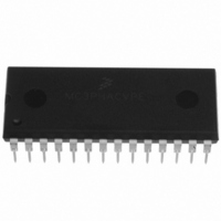
MC3PHACVPE Freescale Semiconductor, MC3PHACVPE Datasheet - Page 7

MC3PHACVPE
Manufacturer Part Number
MC3PHACVPE
Description
IC MOTOR CONTROLLER 28-DIP
Manufacturer
Freescale Semiconductor
Datasheet
1.MC3PHACVFAE.pdf
(36 pages)
Specifications of MC3PHACVPE
Applications
AC Motor Controller, 3 Phase
Number Of Outputs
1
Voltage - Supply
4.5 V ~ 5.5 V
Operating Temperature
-40°C ~ 105°C
Mounting Type
Through Hole
Package / Case
28-DIP (0.600", 15.24mm)
Processor Series
MC3PHAC
Core
HC08
Data Bus Width
8 bit
Program Memory Type
Flash
Program Memory Size
8 KB
Data Ram Size
256 KB
Interface Type
RS-232
Maximum Clock Frequency
21.16 KHz
Number Of Programmable I/os
14
Number Of Timers
1
Operating Supply Voltage
5 V
Maximum Operating Temperature
+ 105 C
Mounting Style
Through Hole
Minimum Operating Temperature
- 40 C
On-chip Adc
10 bit, 4 Channel
Controller Family/series
HC08
Core Size
8 Bit
Ram Memory Size
256Byte
Embedded Interface Type
SCI
Digital Ic Case Style
DIP
No. Of Pins
28
A/d Converter
10 Bits
No. Of Timers 8/12/16/32 Bits
0/0/2/0
Rohs Compliant
Yes
Lead Free Status / RoHS Status
Lead free / RoHS Compliant
Current - Output
-
Voltage - Load
-
Lead Free Status / Rohs Status
Lead free / RoHS Compliant
Available stocks
Company
Part Number
Manufacturer
Quantity
Price
Company:
Part Number:
MC3PHACVPE
Manufacturer:
TE
Quantity:
1 001
Freescale Semiconductor
Number
1. Correct timing of the MC3PHAC is based on a 4.00 MHz crystal or ceramic resonator. Follow the crystal/resonator
Pin
manufacturer’s recommendations, as the crystal/resonator parameters determine the external component values required
for maximum stability and reliable starting. The load capacitance values used in the oscillator circuit design should include
all stray capacitances.
17
18
19
20
21
22
23
24
25
26
27
28
VBOOST_MODE
DT_FAULTOUT
RETRY_TxD
Pin Name
RBRAKE
DC_BUS
MUX_IN
SPEED
ACCEL
START
FWD
V
V
DD
SS
Table 2. MC3PHAC Pin Descriptions (Sheet 2 of 2)
MC3PHAC Monolithic Intelligent Motor Controller, Rev. 2
In standalone mode, this pin is an output that drives low to indicate the
Output which is driven to a logic high whenever the voltage on the dc bus
In standalone mode, this pin is an output which drives low to indicate the
At startup, this input is sampled to determine whether to enter standalone
+5-volt digital power supply to the MC3PHAC
Digital power supply ground return for the MC3PHAC
Input which is sampled to determine whether the motor should rotate in
Input which is sampled to determine whether the motor should be
In standalone mode, during initialization this pin is an output that is used
In standalone mode, during initialization this pin is an output that is used
In standalone mode, during initialization this pin is an output that is used
In standalone mode, during initialization this pin is an output that is used
parameter mux input pin is reading an analog voltage to specify the time
to wait after a fault before re-enabling the PWM outputs. In PC master
software mode, this pin is an output that transmits UART serial data.
input pin exceeds a preset level, indicating a high bus voltage. This
signal is intended to connect a resistor across the dc bus capacitor to
prevent excess capacitor voltage.
parameter mux input pin is reading an analog voltage to specify the
dead-time between the on states of the top and bottom PWM signals for
a given motor phase. In PC master software mode, this pin is an output
which goes low whenever a fault condition occurs.
mode (logic high) or PC master software mode (logic low). In
standalone mode, this pin is also used as an output that drives low to
indicate the parameter mux input pin is reading an analog voltage to
specify the amount of voltage boost to apply to the motor.
the forward or reverse direction
running.
to determine PWM polarity and base frequency. Otherwise, it is an
analog input used to read several voltage levels that specify MC3PHAC
operating parameters.
to determine PWM polarity and base frequency. Otherwise, it is an
analog input used to read a voltage level corresponding to the desired
steady-state speed of the motor.
to determine PWM polarity and base frequency. Otherwise, it is an
analog input used to read a voltage level corresponding to the desired
acceleration of the motor.
to determine PWM polarity and base frequency. Otherwise, it is an
analog input used to read a voltage level proportional to the dc bus
voltage.
Pin Function
Pin Descriptions
7


