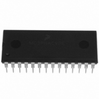
MC3PHACVPE Freescale Semiconductor, MC3PHACVPE Datasheet - Page 9

MC3PHACVPE
Manufacturer Part Number
MC3PHACVPE
Description
IC MOTOR CONTROLLER 28-DIP
Manufacturer
Freescale Semiconductor
Datasheet
1.MC3PHACVFAE.pdf
(36 pages)
Specifications of MC3PHACVPE
Applications
AC Motor Controller, 3 Phase
Number Of Outputs
1
Voltage - Supply
4.5 V ~ 5.5 V
Operating Temperature
-40°C ~ 105°C
Mounting Type
Through Hole
Package / Case
28-DIP (0.600", 15.24mm)
Processor Series
MC3PHAC
Core
HC08
Data Bus Width
8 bit
Program Memory Type
Flash
Program Memory Size
8 KB
Data Ram Size
256 KB
Interface Type
RS-232
Maximum Clock Frequency
21.16 KHz
Number Of Programmable I/os
14
Number Of Timers
1
Operating Supply Voltage
5 V
Maximum Operating Temperature
+ 105 C
Mounting Style
Through Hole
Minimum Operating Temperature
- 40 C
On-chip Adc
10 bit, 4 Channel
Controller Family/series
HC08
Core Size
8 Bit
Ram Memory Size
256Byte
Embedded Interface Type
SCI
Digital Ic Case Style
DIP
No. Of Pins
28
A/d Converter
10 Bits
No. Of Timers 8/12/16/32 Bits
0/0/2/0
Rohs Compliant
Yes
Lead Free Status / RoHS Status
Lead free / RoHS Compliant
Current - Output
-
Voltage - Load
-
Lead Free Status / Rohs Status
Lead free / RoHS Compliant
Available stocks
Company
Part Number
Manufacturer
Quantity
Price
Company:
Part Number:
MC3PHACVPE
Manufacturer:
TE
Quantity:
1 001
Features
High Precision Calculations — Up to 32-bit variable resolution is employed for precision control and
smooth performance. For example, the motor speed can be controlled with a resolution of 4 mHz.
Smooth Voltage Transitions — When the commanded speed of the motor passes through ±1 Hz, the
voltage is gently applied or removed depending on the direction of the speed change. This eliminates any
pops or surges that may occur, especially under conditions of high-voltage boost at low frequencies.
High-Side Bootstrapping — Many motor drive topologies (especially high-voltage drives) use
optocouplers to supply the PWM signal to the high-side transistors. Often, the high-side transistor drive
circuitry contains a charge pump circuit to create a floating power supply for each high-side transistor that
is dependent on low-side PWMs to develop power. When the motor has been off for a period of time, the
charge on the high-side power supply capacitor is depleted and must be replenished before proper PWM
operation can resume.
To accommodate such topologies, the MC3PHAC will always provide 100 ms of 50 percent PWM drive
to only the low-side transistors each time the motor is turned on. Since the top transistors remain off
during this time, it has the effect of applying zero volts to the motor, and no motion occurs. After this
period, motor waveform modulation begins, with PWM drive also being applied to the high-side
transistors.
Fast Velocity Updating — During periods when the motor speed is changing, the rate at which the
velocity is updated is critical to smooth operation. If these updates occur too infrequently, a ratcheting
effect will be exhibited on the motor, which inhibits smooth torque performance. However, velocity
profiling is a very calculation intensive operation to perform, which runs contrary to the previous
requirement.
In the MC3PHAC, a velocity pipelining technique is employed which allows linear interpolation of the
velocity values, resulting in a new velocity value every 189 µs (252 µs for 15.9 kHz PWMs). The net result
is ultra smooth velocity transitions, where each velocity step is not perceivable by the motor.
Dynamic Bus Ripple Cancellation — The dc bus voltage is sensed by the MC3PHAC, and any
deviations from a predetermined norm (3.5 V on the dc bus input pin) result in corrections to the PWM
values to counteract the effect of the bus voltage changes on the motor current. The frequency of this
calculation is sufficiently high to permit compensation for line frequency ripple, as well as slower bus
voltage changes resulting from regeneration or brown out conditions. See
Figure
4.
Selectable Base Frequency — Alternating current (ac) motors are designed to accept rated voltage at
either 50 or 60 Hz, depending on what region of the world they were designed to be used. The MC3PHAC
can accommodate both types of motors by allowing the voltage profile to reach maximum value at either
50 or 60 Hz. This parameter can be specified at initialization in standalone mode, or it can be changed at
any time in PC master software mode.
Selectable PWM Polarity — The polarity of the PWM outputs may be specified such that a logic high on
a PWM output can either be the asserted or negated state of the signal. In standalone mode, this
parameter is specified at initialization and applies to all six PWM outputs. In PC master software mode,
the polarity of the top PWM signals can be specified separately from the polarity of the bottom PWM
signals.
This specification can be done at any time, but once it is done, the polarities are locked and cannot be
changed until a reset occurs. Also, any commands from PC master software that would have the effect
of enabling PWMs are prevented by the MC3PHAC until the polarity has been specified.
MC3PHAC Monolithic Intelligent Motor Controller, Rev. 2
Freescale Semiconductor
9


