IS-DEM KIT-1 NKK Switches, IS-DEM KIT-1 Datasheet - Page 8
IS-DEM KIT-1
Manufacturer Part Number
IS-DEM KIT-1
Description
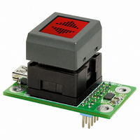
SMARTSWITCH DEMONSTRATION KIT 1
Manufacturer
NKK Switches
Series
SmartSwitch™r
Datasheet
1.IS-DEM_KIT-1.pdf
(8 pages)
Specifications of IS-DEM KIT-1
Main Purpose
Switches with Programmable Display
Utilized Ic / Part
SmartSwitch™LCD Switch
Primary Attributes
Red/Green SmartSwitch™
Secondary Attributes
Bitmaps, up to 63
Description/function
SMARTSWITCH Development Kit
Architecture
Universal Communicator
Board Size
1.752 in x 0.965 in
Maximum Operating Temperature
+ 40 C
Minimum Operating Temperature
0 C
Operating Voltage
5 V
Supply Current
150 mA
For Use With
360-2324 - BATTERY BOX FOR DEM KITS
Lead Free Status / RoHS Status
Not applicable / Not applicable
Embedded
-
Lead Free Status / Rohs Status
Lead free / RoHS Compliant
For Use With/related Products
Smart Switch - LCD Switch
Other names
360-2322


DEMONSTRATION KIT SPECIFICATIONS
Typical Electrical Characteristics
Ratings
8
SMARTSWITCH
Backlight Color
Forward Current
Forward Voltage
Supply Voltage for Logics
Input Voltage
Current
Operating Temperature Range
Storage Temperature Range
IS15AACP4CF
Part Number
(Temperature at 25°C)
Standard LED Backlighting
Items
TM
STN Positive
LCD Mode
Yellow
SENSITIVE DEVICES
ELECTROSTATIC
ATTENTION
(Temperature at 25°C)
Symbols
Symbols
Red/Green
LED Color
I
V
V
V
I
T
T
F
DD
OP
ST
DD
I
F
5.0V ±10%
0 ~ 5.25V
~ 150mA
0 ~ 40°C
0 ~ 60°C
0 ~ 28V
Ratings
SMARTDISPLAY
Part Number
IS01BCCF
Red/Green
Super Bright LED Backlighting
2.1/2.2
15/15
Supplied by USB while connected to PC
Header connector pins 11 ~ 16
Header connector pin 2
STN Positive
LCD Mode
TM
Yellow
Description
SENSITIVE DEVICES
ELECTROSTATIC
ATTENTION
Red/Green
LED Color
Unit
mA
V
PIN CONFIGURATIONS
Pin No. Symbol
3 4
10
11
12
13
14
15
16
1
2
5
6
7
8
9
LED_com
LED_1k
LED_2k
LED_1c
LED_2c
Disp_2
Disp_3
Disp_4
Disp_5
Disp_6
Disp_1
SW 1
SW 2
V
V
DD
SS
Bitmap number set bit1
Bitmap number set bit2
Bitmap number set bit3
Bitmap number set bit4
Bitmap number set bit5
Bitmap number set bit6
(Open Collector)
LED 1 (cathode)
LED 2 (cathode)
(Open Collector)
LED 1 Control
LED 2 Control
LED common
Switch 1
Switch 2
* See Control of Data on next page
(anode)
Ground
MSB bit
LSB bit
Name
Power
}
Supply +5.0V (When connected to PC via
USB, do not supply the controller with another
external power.)
Common anode of backlight LEDs of IS
External power supply terminal for drive of LEDs
GND terminal
IS15: Connected to switch terminal 1; IS01:
no connection
IS15: Connected to switch terminal 2; IS01:
no connection
Cathode terminal of backlight LED 1
Cathode terminal of backlight LED 2
Output terminal for backlight control set by
“IS Easy Editor”
* Connected to LED_1k terminal via resistor
for current limitation
Output terminal for backlight control set by
“IS Easy Editor”
* Connected to LED_2k terminal via resistor
for current limitation
Function
0; Low (L) Level = 0 ~ 0.8V
1; High (H) Level = 2 ~ 5.25V
9
Related parts for IS-DEM KIT-1
Image
Part Number
Description
Manufacturer
Datasheet
Request
R

Part Number:
Description:
SMARTDISPLAY DEMONSTRATION KIT 2
Manufacturer:
NKK Switches
Datasheet:

Part Number:
Description:
SMARTSWITCH INT DEMONSTRATN KIT1
Manufacturer:
NKK Switches
Part Number:
Description:
SMARTSWITCH INT DEMONSTRATN KIT2
Manufacturer:
NKK Switches

Part Number:
Description:
Rocker Switches & Paddle Switches High In-rush Rated Rocker Switch
Manufacturer:
NKK Switches
Datasheet:
Part Number:
Description:
Rocker Switches & Paddle Switches High In-rush Rated Rocker Switch
Manufacturer:
NKK Switches
Datasheet:
Part Number:
Description:
Rocker Switches & Paddle Switches High In-rush Rated Rocker Switch
Manufacturer:
NKK Switches
Datasheet:
Part Number:
Description:
Rocker Switches & Paddle Switches High In-rush Rated Rocker Switch
Manufacturer:
NKK Switches
Datasheet:

Part Number:
Description:
Pushbutton Switches SPST ON(OFF) 15/32'
Manufacturer:
NKK Switches
Datasheet:

Part Number:
Description:
Pushbutton Switches SPST OFF(ON) 15/32'
Manufacturer:
NKK Switches
Datasheet:

Part Number:
Description:
Pushbutton Switches ON(OFF) NORM CLSD 3A RED PLNGR LUG 15/32
Manufacturer:
NKK Switches
Datasheet:
Part Number:
Description:
Pushbutton Switches SPDT ON-(ON)
Manufacturer:
NKK Switches
Datasheet:

Part Number:
Description:
Pushbutton Switches ON-(ON) RND BUSH MNT RED LED RED/RED CAP
Manufacturer:
NKK Switches
Datasheet:
Part Number:
Description:
Pushbutton Switches SPST ON-(OFF) STRT
Manufacturer:
NKK Switches
Datasheet:
Part Number:
Description:
Pushbutton Switches OFF(ON) NORM OPEN 3A RED CAP LUG 15/32
Manufacturer:
NKK Switches
Datasheet:
Part Number:
Description:
Pushbutton Switches ILLUM PUSHBUTTON SPDT
Manufacturer:
NKK Switches
Datasheet: