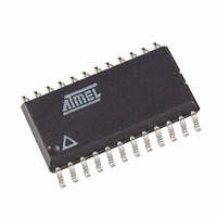
T89C51CC02CA-TDSIM Atmel, T89C51CC02CA-TDSIM Datasheet - Page 41

T89C51CC02CA-TDSIM
Manufacturer Part Number
T89C51CC02CA-TDSIM
Description
IC 8051 MCU FLASH 16K 24SOIC
Manufacturer
Atmel
Series
AT89C CANr
Datasheets
1.T89C51CC02CA-TDSIM.pdf
(159 pages)
2.T89C51CC02CA-TDSIM.pdf
(33 pages)
3.T89C51CC02CA-TDSIM.pdf
(29 pages)
4.T89C51CC02CA-TDSIM.pdf
(148 pages)
Specifications of T89C51CC02CA-TDSIM
Core Processor
8051
Core Size
8-Bit
Speed
40MHz
Connectivity
CAN, UART/USART
Peripherals
POR, PWM, WDT
Number Of I /o
20
Program Memory Size
16KB (16K x 8)
Program Memory Type
FLASH
Eeprom Size
2K x 8
Ram Size
512 x 8
Voltage - Supply (vcc/vdd)
3 V ~ 5.5 V
Data Converters
A/D 8x10b
Oscillator Type
External
Operating Temperature
-40°C ~ 85°C
Package / Case
24-SOIC (7.5mm Width)
For Use With
AT89STK-06 - KIT DEMOBOARD 8051 MCU W/CAN
Lead Free Status / RoHS Status
Contains lead / RoHS non-compliant
Other names
T89C51CC02CATDSIM
- T89C51CC02CA-TDSIM PDF datasheet
- T89C51CC02CA-TDSIM PDF datasheet #2
- T89C51CC02CA-TDSIM PDF datasheet #3
- T89C51CC02CA-TDSIM PDF datasheet #4
- Current page: 41 of 159
- Download datasheet (2Mb)
Flash Protection from Parallel
Programming
Preventing Flash Corruption
4126L–CAN–01/08
Figure 17. Reading Procedure
Note:
The three lock bits in Hardware Security Byte (See ’In-System Programming’ section)
are programmed according to Table 24 provide different level of protection for the on-
chip code and data located in FM0 and FM1.
The only way to write this bits are the parallel mode. They are set by default to level 3.
Table 24. Program Lock bit
Note:
WARNING: Security level 2, 3 and 4 should only be programmed after Flash and Core
verification.
See Section “Power Management”.
Security
Level
1
2
3
4
Program Lock bits
aa = 10 for the Hardware Security Byte.
1. Program Lock bits
U: unprogrammed
P: programmed
LB0
U
P
U
U
LB1
U
U
P
U
LB2
U
U
U
P
Protection Description
No program lock features enabled.
Parallel programming of the Flash is disabled.
Same as 2, also verify through parallel programming interface is
disabled. This is the factory defaul programming.
Same as 3
Exec: MOVC A, @A+DPTR
Flash Spaces Reading
Flash Spaces Mapping
FCON = 00000aa0b
DPTR = Address
FCON = 00h
Clear Mode
Data Read
ACC= 0
AT/T89C51CC02
41
Related parts for T89C51CC02CA-TDSIM
Image
Part Number
Description
Manufacturer
Datasheet
Request
R

Part Number:
Description:
8-Bit MCU
Manufacturer:
Atmel
Datasheet:

Part Number:
Description:
DEV KIT FOR AVR/AVR32
Manufacturer:
Atmel
Datasheet:

Part Number:
Description:
INTERVAL AND WIPE/WASH WIPER CONTROL IC WITH DELAY
Manufacturer:
ATMEL Corporation
Datasheet:

Part Number:
Description:
Low-Voltage Voice-Switched IC for Hands-Free Operation
Manufacturer:
ATMEL Corporation
Datasheet:

Part Number:
Description:
MONOLITHIC INTEGRATED FEATUREPHONE CIRCUIT
Manufacturer:
ATMEL Corporation
Datasheet:

Part Number:
Description:
AM-FM Receiver IC U4255BM-M
Manufacturer:
ATMEL Corporation
Datasheet:

Part Number:
Description:
Monolithic Integrated Feature Phone Circuit
Manufacturer:
ATMEL Corporation
Datasheet:

Part Number:
Description:
Multistandard Video-IF and Quasi Parallel Sound Processing
Manufacturer:
ATMEL Corporation
Datasheet:

Part Number:
Description:
High-performance EE PLD
Manufacturer:
ATMEL Corporation
Datasheet:

Part Number:
Description:
8-bit Flash Microcontroller
Manufacturer:
ATMEL Corporation
Datasheet:

Part Number:
Description:
2-Wire Serial EEPROM
Manufacturer:
ATMEL Corporation
Datasheet:


