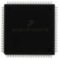
MC9S12E128CPVE Freescale Semiconductor, MC9S12E128CPVE Datasheet - Page 297

MC9S12E128CPVE
Manufacturer Part Number
MC9S12E128CPVE
Description
IC MCU 128K FLASH 25MHZ 112-LQFP
Manufacturer
Freescale Semiconductor
Series
HCS12r
Specifications of MC9S12E128CPVE
Core Processor
HCS12
Core Size
16-Bit
Speed
25MHz
Connectivity
EBI/EMI, I²C, SCI, SPI
Peripherals
POR, PWM, WDT
Number Of I /o
91
Program Memory Size
128KB (128K x 8)
Program Memory Type
FLASH
Ram Size
8K x 8
Voltage - Supply (vcc/vdd)
2.35 V ~ 2.75 V
Data Converters
A/D 16x10b; D/A 2x8b
Oscillator Type
Internal
Operating Temperature
-40°C ~ 85°C
Package / Case
112-LQFP
Processor Series
S12E
Core
HCS12
Data Bus Width
16 bit
Data Ram Size
8 KB
Interface Type
SCI/SPI
Maximum Clock Frequency
25 MHz
Number Of Programmable I/os
92
Number Of Timers
12
Operating Supply Voltage
3.135 V to 5.5 V
Maximum Operating Temperature
+ 85 C
Mounting Style
SMD/SMT
3rd Party Development Tools
EWHCS12
Minimum Operating Temperature
- 40 C
On-chip Adc
16-ch x 10-bit
On-chip Dac
2-ch x 8-bit
Controller Family/series
HCS12/S12X
No. Of I/o's
90
Ram Memory Size
8KB
Cpu Speed
25MHz
No. Of Timers
4
Embedded Interface Type
I2C, SCI, SPI
Rohs Compliant
Yes
For Use With
M68EVB912E128 - BOARD EVAL FOR MC9S12E128/64
Lead Free Status / RoHS Status
Lead free / RoHS Compliant
Eeprom Size
-
Lead Free Status / Rohs Status
Lead free / RoHS Compliant
Available stocks
Company
Part Number
Manufacturer
Quantity
Price
Company:
Part Number:
MC9S12E128CPVE
Manufacturer:
Freescale Semiconductor
Quantity:
10 000
- Current page: 297 of 606
- Download datasheet (4Mb)
9.5
The reset values of registers and signals are described in the Memory Map and Registers section (see
Section 9.3, “Memory Map and Register
9.6
The SPIV3 only originates interrupt requests when SPI is enabled (SPE bit in SPICR1 set). The following
is a description of how the SPIV3 makes a request and how the MCU should acknowledge that request.
The interrupt vector offset and interrupt priority are chip dependent.
The interrupt flags MODF, SPIF and SPTEF are logically ORed to generate an interrupt request.
9.6.1
MODF occurs when the master detects an error on the SS pin. The master SPI must be configured for the
MODF feature (see
changed:
The MODF interrupt is reflected in the status register MODF flag. Clearing the flag will also clear the
interrupt. This interrupt will stay active while the MODF flag is set. MODF has an automatic clearing
process which is described in
9.6.2
SPIF occurs when new data has been received and copied to the SPI Data Register. After SPIF is set, it
does not clear until it is serviced. SPIF has an automatic clearing process which is described in
Section 9.3.2.4, “SPI Status Register (SPISR).”
the next transfer (i.e. SPIF remains active throughout another transfer), the latter transfers will be ignored
and no new data will be copied into the SPIDR.
9.6.3
SPTEF occurs when the SPI Data Register is ready to accept new data. After SPTEF is set, it does not clear
until it is serviced. SPTEF has an automatic clearing process which is described in
Status Register (SPISR).”
Freescale Semiconductor
•
•
•
If a data transmission occurs in slave mode after reset without a write to SPIDR, it will transmit
garbage, or the byte last received from the master before the reset.
Reading from the SPIDR after reset will always read a byte of zeros.
MSTR = 0, The master bit in SPICR1 resets.
Reset
Interrupts
MODF
SPIF
SPTEF
Table
9-3). After MODF is set, the current transfer is aborted and the following bit is
Section 9.3.2.4, “SPI Status Register (SPISR).”
MC9S12E128 Data Sheet, Rev. 1.07
Definition”) which details the registers and their bit-fields.
In the event that the SPIF is not serviced before the end of
Chapter 9 Serial Peripheral Interface (SPIV3)
Section 9.3.2.4, “SPI
297
Related parts for MC9S12E128CPVE
Image
Part Number
Description
Manufacturer
Datasheet
Request
R
Part Number:
Description:
Manufacturer:
Freescale Semiconductor, Inc
Datasheet:
Part Number:
Description:
Manufacturer:
Freescale Semiconductor, Inc
Datasheet:
Part Number:
Description:
Manufacturer:
Freescale Semiconductor, Inc
Datasheet:
Part Number:
Description:
Manufacturer:
Freescale Semiconductor, Inc
Datasheet:
Part Number:
Description:
Manufacturer:
Freescale Semiconductor, Inc
Datasheet:
Part Number:
Description:
Manufacturer:
Freescale Semiconductor, Inc
Datasheet:
Part Number:
Description:
Manufacturer:
Freescale Semiconductor, Inc
Datasheet:
Part Number:
Description:
Manufacturer:
Freescale Semiconductor, Inc
Datasheet:
Part Number:
Description:
Manufacturer:
Freescale Semiconductor, Inc
Datasheet:
Part Number:
Description:
Manufacturer:
Freescale Semiconductor, Inc
Datasheet:
Part Number:
Description:
Manufacturer:
Freescale Semiconductor, Inc
Datasheet:
Part Number:
Description:
Manufacturer:
Freescale Semiconductor, Inc
Datasheet:
Part Number:
Description:
Manufacturer:
Freescale Semiconductor, Inc
Datasheet:
Part Number:
Description:
Manufacturer:
Freescale Semiconductor, Inc
Datasheet:
Part Number:
Description:
Manufacturer:
Freescale Semiconductor, Inc
Datasheet:


