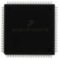
MC9S12E128CPVE Freescale Semiconductor, MC9S12E128CPVE Datasheet - Page 495

MC9S12E128CPVE
Manufacturer Part Number
MC9S12E128CPVE
Description
IC MCU 128K FLASH 25MHZ 112-LQFP
Manufacturer
Freescale Semiconductor
Series
HCS12r
Specifications of MC9S12E128CPVE
Core Processor
HCS12
Core Size
16-Bit
Speed
25MHz
Connectivity
EBI/EMI, I²C, SCI, SPI
Peripherals
POR, PWM, WDT
Number Of I /o
91
Program Memory Size
128KB (128K x 8)
Program Memory Type
FLASH
Ram Size
8K x 8
Voltage - Supply (vcc/vdd)
2.35 V ~ 2.75 V
Data Converters
A/D 16x10b; D/A 2x8b
Oscillator Type
Internal
Operating Temperature
-40°C ~ 85°C
Package / Case
112-LQFP
Processor Series
S12E
Core
HCS12
Data Bus Width
16 bit
Data Ram Size
8 KB
Interface Type
SCI/SPI
Maximum Clock Frequency
25 MHz
Number Of Programmable I/os
92
Number Of Timers
12
Operating Supply Voltage
3.135 V to 5.5 V
Maximum Operating Temperature
+ 85 C
Mounting Style
SMD/SMT
3rd Party Development Tools
EWHCS12
Minimum Operating Temperature
- 40 C
On-chip Adc
16-ch x 10-bit
On-chip Dac
2-ch x 8-bit
Controller Family/series
HCS12/S12X
No. Of I/o's
90
Ram Memory Size
8KB
Cpu Speed
25MHz
No. Of Timers
4
Embedded Interface Type
I2C, SCI, SPI
Rohs Compliant
Yes
For Use With
M68EVB912E128 - BOARD EVAL FOR MC9S12E128/64
Lead Free Status / RoHS Status
Lead free / RoHS Compliant
Eeprom Size
-
Lead Free Status / Rohs Status
Lead free / RoHS Compliant
Available stocks
Company
Part Number
Manufacturer
Quantity
Price
Company:
Part Number:
MC9S12E128CPVE
Manufacturer:
Freescale Semiconductor
Quantity:
10 000
- Current page: 495 of 606
- Download datasheet (4Mb)
16.4.1.4
The original BKP_ST12_A module supports two breakpoints. The DBG_ST12_A module can be used in
BKP mode and allow a third breakpoint using comparator C. Four additional bits, BKCEN, TAGC,
RWCEN, and RWC in DBGC2 in conjunction with additional comparator C address registers, DBGCCX,
DBGCCH, and DBGCCL allow the user to set up a third breakpoint. Using PAGSEL in DBGCCX for
expanded memory will work differently than the way paged memory is done using comparator A and B in
BKP mode. See
information on using comparator C.
16.4.2
Enabling the DBG module in DBG mode, allows the arming, triggering, and storing of data in the trace
buffer and can be used to cause CPU breakpoints. The DBG module is made up of three main blocks, the
comparators, trace buffer control logic, and the trace buffer.
16.4.2.1
The DBG contains three comparators, A, B, and C. Comparator A compares the core address bus with the
address stored in DBGCAH and DBGCAL. Comparator B compares the core address bus with the address
stored in DBGCBH and DBGCBL except in full mode, where it compares the data buses to the data stored
in DBGCBH and DBGCBL. Comparator C can be used as a breakpoint generator or as the address
comparison unit in the loop1 mode. Matches on comparator A, B, and C are signaled to the trace buffer
Freescale Semiconductor
DBG Operating in DBG Mode
Using Comparator C in BKP Mode
Comparators
BDM should not be entered from a breakpoint unless the ENABLE bit is set
in the BDM. Even if the ENABLE bit in the BDM is cleared, the CPU
actually executes the BDM firmware code. It checks the ENABLE and
returns if ENABLE is not set. If the BDM is not serviced by the monitor then
the breakpoint would be re-asserted when the BDM returns to normal CPU
flow.
There is no hardware to enforce restriction of breakpoint operation if the
BDM is not enabled.
When program control returns from a tagged breakpoint through an RTI or
a BDM GO command, it will return to the instruction whose tag generated
the breakpoint. Unless breakpoints are disabled or modified in the service
routine or active BDM session, the instruction will be tagged again and the
breakpoint will be repeated. In the case of BDM breakpoints, this situation
can also be avoided by executing a TRACE1 command before the GO to
increment the program flow past the tagged instruction.
In general, there is a latency between the triggering event appearing on the
bus and being detected by the DBG circuitry. In general, tagged triggers will
be more predictable than forced triggers.
Section 16.3.2.5, “Debug Comparator C Extended Register
MC9S12E128 Data Sheet, Rev. 1.07
NOTE
NOTE
(DBGCCX),” for more
Chapter 16 Debug Module (DBGV1)
495
Related parts for MC9S12E128CPVE
Image
Part Number
Description
Manufacturer
Datasheet
Request
R
Part Number:
Description:
Manufacturer:
Freescale Semiconductor, Inc
Datasheet:
Part Number:
Description:
Manufacturer:
Freescale Semiconductor, Inc
Datasheet:
Part Number:
Description:
Manufacturer:
Freescale Semiconductor, Inc
Datasheet:
Part Number:
Description:
Manufacturer:
Freescale Semiconductor, Inc
Datasheet:
Part Number:
Description:
Manufacturer:
Freescale Semiconductor, Inc
Datasheet:
Part Number:
Description:
Manufacturer:
Freescale Semiconductor, Inc
Datasheet:
Part Number:
Description:
Manufacturer:
Freescale Semiconductor, Inc
Datasheet:
Part Number:
Description:
Manufacturer:
Freescale Semiconductor, Inc
Datasheet:
Part Number:
Description:
Manufacturer:
Freescale Semiconductor, Inc
Datasheet:
Part Number:
Description:
Manufacturer:
Freescale Semiconductor, Inc
Datasheet:
Part Number:
Description:
Manufacturer:
Freescale Semiconductor, Inc
Datasheet:
Part Number:
Description:
Manufacturer:
Freescale Semiconductor, Inc
Datasheet:
Part Number:
Description:
Manufacturer:
Freescale Semiconductor, Inc
Datasheet:
Part Number:
Description:
Manufacturer:
Freescale Semiconductor, Inc
Datasheet:
Part Number:
Description:
Manufacturer:
Freescale Semiconductor, Inc
Datasheet:


