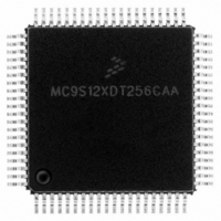
MC9S12XDT256CAA Freescale Semiconductor, MC9S12XDT256CAA Datasheet - Page 770

MC9S12XDT256CAA
Manufacturer Part Number
MC9S12XDT256CAA
Description
IC MCU 256K FLASH 80-QFP
Manufacturer
Freescale Semiconductor
Series
HCS12r
Datasheet
1.MC9S12XD64CAA.pdf
(1348 pages)
Specifications of MC9S12XDT256CAA
Core Processor
HCS12X
Core Size
16-Bit
Speed
80MHz
Connectivity
CAN, EBI/EMI, I²C, IrDA, LIN, SCI, SPI
Peripherals
LVD, POR, PWM, WDT
Number Of I /o
59
Program Memory Size
256KB (256K x 8)
Program Memory Type
FLASH
Eeprom Size
4K x 8
Ram Size
16K x 8
Voltage - Supply (vcc/vdd)
2.35 V ~ 5.5 V
Data Converters
A/D 8x10b
Oscillator Type
External
Operating Temperature
-40°C ~ 85°C
Package / Case
80-QFP
Processor Series
S12XD
Core
HCS12
Data Bus Width
16 bit
Data Ram Size
16 KB
Interface Type
CAN/I2C/SCI/SPI
Maximum Clock Frequency
40 MHz
Number Of Programmable I/os
59
Number Of Timers
12
Maximum Operating Temperature
+ 85 C
Mounting Style
SMD/SMT
3rd Party Development Tools
EWHCS12
Development Tools By Supplier
EVB9S12XDP512E
Minimum Operating Temperature
- 40 C
On-chip Adc
8-ch x 10-bit
Lead Free Status / RoHS Status
Lead free / RoHS Compliant
Available stocks
Company
Part Number
Manufacturer
Quantity
Price
Company:
Part Number:
MC9S12XDT256CAA
Manufacturer:
Freescale Semiconductor
Quantity:
10 000
Company:
Part Number:
MC9S12XDT256CAAR
Manufacturer:
Freescale Semiconductor
Quantity:
10 000
- Current page: 770 of 1348
- Download datasheet (8Mb)
Chapter 20 S12X Debug (S12XDBGV3) Module
match condition requires that a valid match for both comparators happens on the same bus cycle. A match
condition on only one comparator is not valid. An aligned word access which straddles the range boundary
will cause a trigger only if the aligned address is inside the range.
20.4.2.3.2
In the Outside Range comparator mode, either comparator pair A and B or comparator pair C and D can
be configured for range comparisons. A single match condition on either of the comparators is recognized
as valid. An aligned word access which straddles the range boundary will cause a trigger only if the aligned
address is outside the range.
Outside range mode in combination with tagged triggers can be used to detect if the opcode fetches are
from an unexpected range. In forced trigger modes the outside range trigger would typically be activated
at any interrupt vector fetch or register access. This can be avoided by setting the upper range limit to
$7FFFFF or lower range limit to $000000 respectively.
When comparing the XGATE address bus in outside range mode, the initial vector fetch as determined by
the vector contained in the XGATE XGVBR register should be taken into consideration. The XGVBR
register and hence vector address can be modified.
20.4.3
Trigger modes are used as qualifiers for a state sequencer change of state. The control logic determines the
trigger mode and provides a trigger to the state sequencer. The individual trigger modes are described in
the following sections.
20.4.3.1
If a forced trigger comparator match occurs, the trigger immediately initiates a transition to the next state
sequencer state whereby the corresponding flags in DBGSR are set. The state control register for the
current state determines the next state for each trigger. Forced triggers are generated as soon as the
matching address appears on the address bus, which in the case of opcode fetches occurs several cycles
before the opcode execution. For this reason a forced trigger of an opcode address precedes a tagged trigger
at the same address by several cycles.
20.4.3.2
If either a S12XCPU or XGATE taghit occurs a transition to another state sequencer state is initiated and
the corresponding DBGSR flags are set. For a comparator related taghit to occur, the S12XDBG must first
generate tags based on comparator matches. When the tagged instruction reaches the execution stage of
the instruction queue a taghit is generated by the S12XCPU/XGATE. The state control register for the
current state determines the next state for each trigger.
20.4.3.3
In external tagging trigger mode, the TAGLO and TAGHI pins (mapped to device pins) are used to tag an
instruction. This function can be used as another breakpoint source. When the tagged opcode reaches the
772
Trigger Modes
Forced Trigger On Comparator Match
Trigger On Comparator Related Taghit
External Tagging Trigger
Outside Range (address < CompAC_Addr or address > CompBD_Addr)
MC9S12XDP512 Data Sheet, Rev. 2.21
Freescale Semiconductor
Related parts for MC9S12XDT256CAA
Image
Part Number
Description
Manufacturer
Datasheet
Request
R

Part Number:
Description:
16-BIT MICROPROCESSOR FAMILY
Manufacturer:
FREESCALE [Freescale Semiconductor, Inc]
Datasheet:
Part Number:
Description:
Manufacturer:
Freescale Semiconductor, Inc
Datasheet:
Part Number:
Description:
Manufacturer:
Freescale Semiconductor, Inc
Datasheet:
Part Number:
Description:
Manufacturer:
Freescale Semiconductor, Inc
Datasheet:
Part Number:
Description:
Manufacturer:
Freescale Semiconductor, Inc
Datasheet:
Part Number:
Description:
Manufacturer:
Freescale Semiconductor, Inc
Datasheet:
Part Number:
Description:
Manufacturer:
Freescale Semiconductor, Inc
Datasheet:
Part Number:
Description:
Manufacturer:
Freescale Semiconductor, Inc
Datasheet:
Part Number:
Description:
Manufacturer:
Freescale Semiconductor, Inc
Datasheet:
Part Number:
Description:
Manufacturer:
Freescale Semiconductor, Inc
Datasheet:
Part Number:
Description:
Manufacturer:
Freescale Semiconductor, Inc
Datasheet:
Part Number:
Description:
Manufacturer:
Freescale Semiconductor, Inc
Datasheet:
Part Number:
Description:
Manufacturer:
Freescale Semiconductor, Inc
Datasheet:
Part Number:
Description:
Manufacturer:
Freescale Semiconductor, Inc
Datasheet:
Part Number:
Description:
Manufacturer:
Freescale Semiconductor, Inc
Datasheet:


