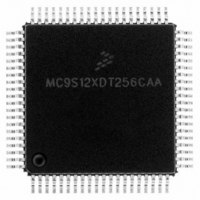
MC9S12XDT256CAA Freescale Semiconductor, MC9S12XDT256CAA Datasheet - Page 773

MC9S12XDT256CAA
Manufacturer Part Number
MC9S12XDT256CAA
Description
IC MCU 256K FLASH 80-QFP
Manufacturer
Freescale Semiconductor
Series
HCS12r
Datasheet
1.MC9S12XD64CAA.pdf
(1348 pages)
Specifications of MC9S12XDT256CAA
Core Processor
HCS12X
Core Size
16-Bit
Speed
80MHz
Connectivity
CAN, EBI/EMI, I²C, IrDA, LIN, SCI, SPI
Peripherals
LVD, POR, PWM, WDT
Number Of I /o
59
Program Memory Size
256KB (256K x 8)
Program Memory Type
FLASH
Eeprom Size
4K x 8
Ram Size
16K x 8
Voltage - Supply (vcc/vdd)
2.35 V ~ 5.5 V
Data Converters
A/D 8x10b
Oscillator Type
External
Operating Temperature
-40°C ~ 85°C
Package / Case
80-QFP
Processor Series
S12XD
Core
HCS12
Data Bus Width
16 bit
Data Ram Size
16 KB
Interface Type
CAN/I2C/SCI/SPI
Maximum Clock Frequency
40 MHz
Number Of Programmable I/os
59
Number Of Timers
12
Maximum Operating Temperature
+ 85 C
Mounting Style
SMD/SMT
3rd Party Development Tools
EWHCS12
Development Tools By Supplier
EVB9S12XDP512E
Minimum Operating Temperature
- 40 C
On-chip Adc
8-ch x 10-bit
Lead Free Status / RoHS Status
Lead free / RoHS Compliant
Available stocks
Company
Part Number
Manufacturer
Quantity
Price
Company:
Part Number:
MC9S12XDT256CAA
Manufacturer:
Freescale Semiconductor
Quantity:
10 000
Company:
Part Number:
MC9S12XDT256CAAR
Manufacturer:
Freescale Semiconductor
Quantity:
10 000
- Current page: 773 of 1348
- Download datasheet (8Mb)
bit in the DBGC1 register is cleared, returning the module to the disarmed state0. If tracing is enabled a
breakpoint request can occur at the end of the tracing session. If neither tracing nor breakpoints are enabled
then when the final state is reached it returns automatically to state0 and the debug module is disarmed.
20.4.5
The trace buffer is a 64 lines deep by 64-bits wide RAM array. The S12XDBG module stores trace
information in the RAM array in a circular buffer format. The S12XCPU accesses the RAM array through
a register window (DBGTBH:DBGTBL) using 16-bit wide word accesses. After each complete 64-bit
trace buffer line is read via the S12XCPU, an internal pointer into the RAM is incremented so that the next
read will receive fresh information. Data is stored in the format shown in
counter register bits DBGCNT[6:0] are incremented. Tracing of S12XCPU activity is disabled when the
BDM is active but tracing of XGATE activity is still possible. Reading the trace buffer whilst the BDM is
active returns invalid data and the trace buffer pointer is not incremented.
20.4.5.1
Using the TALIGN bits (see
or the beginning of a tracing session.
If End or Mid tracing is selected, tracing begins when the ARM bit in DBGC1 is set and State1 is entered.
The transition to Final State if End is selected signals the end of the tracing session. The transition to Final
State if Mid is selected signals that another 32 lines will be traced before ending the tracing session.
Tracing with Begin-Trigger starts at the opcode of the trigger. Using End or Mid-Trigger or when the
tracing is initiated by writing to the TRIG bit whilst configured for Begin-Trigger, tracing starts at the
second opcode after writing to DBGC1 if written in the CPU thread, .
20.4.5.1.1
Storing with Begin-Trigger, data is not stored in the Trace Buffer until the Final State is entered. Once the
trigger condition is met the S12XDBG module will remain armed until 64 lines are stored in the Trace
Buffer. If the trigger is at the address of the change-of-flow instruction the change of flow associated with
the trigger will be stored in the Trace Buffer. Using Begin-trigger together with tagging, if the tagged
instruction is about to be executed then the trace is started. Upon completion of the tracing session the
breakpoint is generated, thus the breakpoint does not occur at the tagged instruction boundary.
20.4.5.1.2
Storing with Mid-Trigger, data is stored in the Trace Buffer as soon as the S12XDBG module is armed.
When the trigger condition is met, another 32 lines will be traced before ending the tracing session,
irrespective of the number of lines stored before the trigger occurred, then the S12XDBG module is
disarmed and no more data is stored. If the trigger is at the address of a change of flow instruction the
trigger event is not stored in the Trace Buffer. Using Mid-trigger with tagging, if the tagged instruction is
about to be executed then the trace is continued for another 32 lines. Upon tracing completion the
breakpoint is generated, thus the breakpoint does not occur at the tagged instruction boundary.
Freescale Semiconductor
Trace Buffer Operation
Trace Trigger Alignment
Storing with Begin-Trigger
Storing with Mid-Trigger
Section
MC9S12XDP512 Data Sheet, Rev. 2.21
20.3.2.3”) it is possible to align the trigger with the end, the middle,
Chapter 20 S12X Debug (S12XDBGV3) Module
Table
20-39. After each store the
775
Related parts for MC9S12XDT256CAA
Image
Part Number
Description
Manufacturer
Datasheet
Request
R

Part Number:
Description:
16-BIT MICROPROCESSOR FAMILY
Manufacturer:
FREESCALE [Freescale Semiconductor, Inc]
Datasheet:
Part Number:
Description:
Manufacturer:
Freescale Semiconductor, Inc
Datasheet:
Part Number:
Description:
Manufacturer:
Freescale Semiconductor, Inc
Datasheet:
Part Number:
Description:
Manufacturer:
Freescale Semiconductor, Inc
Datasheet:
Part Number:
Description:
Manufacturer:
Freescale Semiconductor, Inc
Datasheet:
Part Number:
Description:
Manufacturer:
Freescale Semiconductor, Inc
Datasheet:
Part Number:
Description:
Manufacturer:
Freescale Semiconductor, Inc
Datasheet:
Part Number:
Description:
Manufacturer:
Freescale Semiconductor, Inc
Datasheet:
Part Number:
Description:
Manufacturer:
Freescale Semiconductor, Inc
Datasheet:
Part Number:
Description:
Manufacturer:
Freescale Semiconductor, Inc
Datasheet:
Part Number:
Description:
Manufacturer:
Freescale Semiconductor, Inc
Datasheet:
Part Number:
Description:
Manufacturer:
Freescale Semiconductor, Inc
Datasheet:
Part Number:
Description:
Manufacturer:
Freescale Semiconductor, Inc
Datasheet:
Part Number:
Description:
Manufacturer:
Freescale Semiconductor, Inc
Datasheet:
Part Number:
Description:
Manufacturer:
Freescale Semiconductor, Inc
Datasheet:


