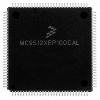
MC9S12XEP100CAL Freescale Semiconductor, MC9S12XEP100CAL Datasheet - Page 593

MC9S12XEP100CAL
Manufacturer Part Number
MC9S12XEP100CAL
Description
IC MCU 16BIT 1M FLASH 112-LQFP
Manufacturer
Freescale Semiconductor
Series
HCS12r
Datasheet
1.MC9S12XEP768CAL.pdf
(1328 pages)
Specifications of MC9S12XEP100CAL
Core Processor
HCS12X
Core Size
16-Bit
Speed
50MHz
Connectivity
CAN, EBI/EMI, I²C, IrDA, SCI, SPI
Peripherals
LVD, POR, PWM, WDT
Number Of I /o
91
Program Memory Size
1MB (1M x 8)
Program Memory Type
FLASH
Eeprom Size
4K x 8
Ram Size
64K x 8
Voltage - Supply (vcc/vdd)
1.72 V ~ 5.5 V
Data Converters
A/D 16x12b
Oscillator Type
External
Operating Temperature
-40°C ~ 85°C
Package / Case
112-LQFP
Processor Series
S12XE
Core
HCS12
Data Bus Width
16 bit
Data Ram Size
64 KB
Interface Type
CAN/SCI/SPI
Maximum Clock Frequency
50 MHz
Number Of Programmable I/os
91
Number Of Timers
25
Maximum Operating Temperature
+ 85 C
Mounting Style
SMD/SMT
3rd Party Development Tools
EWHCS12
Development Tools By Supplier
KIT33812ECUEVME, EVB9S12XEP100, DEMO9S12XEP100
Minimum Operating Temperature
- 40 C
On-chip Adc
16-ch x 12-bit
Package
112LQFP
Family Name
HCS12X
Maximum Speed
50 MHz
Operating Supply Voltage
1.8|2.8|5 V
For Use With
EVB9S12XEP100 - BOARD EVAL FOR MC9S12XEP100DEMO9S12XEP100 - BOARD DEMO FOR MC9S12XEP100
Lead Free Status / RoHS Status
Lead free / RoHS Compliant
Available stocks
Company
Part Number
Manufacturer
Quantity
Price
Company:
Part Number:
MC9S12XEP100CAL
Manufacturer:
TOSHIBA
Quantity:
72
Company:
Part Number:
MC9S12XEP100CAL
Manufacturer:
Freescale Semiconductor
Quantity:
10 000
- Current page: 593 of 1328
- Download datasheet (9Mb)
If it were the case that the IBSWAI bit was cleared when the WAI instruction was executed, the IIC internal
clocks and interface would remain alive, continuing the operation which was currently underway. It is also
possible to configure the IIC such that it will wake up the CPU via an interrupt at the conclusion of the
current operation. See the discussion on the IBIF and IBIE bits in the IBSR and IBCR, respectively.
15.3.1.4
This status register is read-only with exception of bit 1 (IBIF) and bit 4 (IBAL), which are software
clearable.
Freescale Semiconductor
RESERVED
Because of an order from the United States International Trade Commission, BGA-packaged product lines and partnumbers
Reset
indicated here currently are not available from Freescale for import or sale in the United States prior to September 2010
Field
IAAS
IBAL
TCF
IBB
7
6
5
4
3
W
R
Module Base + 0x0003
TCF
Data Transferring Bit — While one byte of data is being transferred, this bit is cleared. It is set by the falling
edge of the 9th clock of a byte transfer. Note that this bit is only valid during or immediately following a transfer
to the IIC module or from the IIC module.
0 Transfer in progress
1 Transfer complete
Addressed as a Slave Bit — When its own specific address (I-bus address register) is matched with the calling
address or it receives the general call address with GCEN== 1,this bit is set.The CPU is interrupted provided the
IBIE is set.Then the CPU needs to check the SRW bit and set its Tx/Rx mode accordingly.Writing to the I-bus
control register clears this bit.
0 Not addressed
1 Addressed as a slave
Bus Busy Bit
0 This bit indicates the status of the bus. When a START signal is detected, the IBB is set. If a STOP signal is
1 Bus is busy
Arbitration Lost — The arbitration lost bit (IBAL) is set by hardware when the arbitration procedure is lost.
Arbitration is lost in the following circumstances:
This bit must be cleared by software, by writing a one to it. A write of 0 has no effect on this bit.
Reserved — Bit 3 of IBSR is reserved for future use. A read operation on this bit will return 0.
IIC Status Register (IBSR)
1
7
detected, IBB is cleared and the bus enters idle state.
1. SDA sampled low when the master drives a high during an address or data transmit cycle.
2. SDA sampled low when the master drives a high during the acknowledge bit of a data receive cycle.
3. A start cycle is attempted when the bus is busy.
4. A repeated start cycle is requested in slave mode.
5. A stop condition is detected when the master did not request it.
IAAS
= Unimplemented or Reserved
0
6
Figure 15-7. IIC Bus Status Register (IBSR)
MC9S12XE-Family Reference Manual Rev. 1.23
Table 15-9. IBSR Field Descriptions
IBB
5
0
IBAL
0
4
Description
Chapter 15 Inter-Integrated Circuit (IICV3) Block Description
0
0
3
SRW
2
0
IBIF
0
1
RXAK
0
0
593
Related parts for MC9S12XEP100CAL
Image
Part Number
Description
Manufacturer
Datasheet
Request
R
Part Number:
Description:
Manufacturer:
Freescale Semiconductor, Inc
Datasheet:
Part Number:
Description:
Manufacturer:
Freescale Semiconductor, Inc
Datasheet:
Part Number:
Description:
Manufacturer:
Freescale Semiconductor, Inc
Datasheet:
Part Number:
Description:
Manufacturer:
Freescale Semiconductor, Inc
Datasheet:
Part Number:
Description:
Manufacturer:
Freescale Semiconductor, Inc
Datasheet:
Part Number:
Description:
Manufacturer:
Freescale Semiconductor, Inc
Datasheet:
Part Number:
Description:
Manufacturer:
Freescale Semiconductor, Inc
Datasheet:
Part Number:
Description:
Manufacturer:
Freescale Semiconductor, Inc
Datasheet:
Part Number:
Description:
Manufacturer:
Freescale Semiconductor, Inc
Datasheet:
Part Number:
Description:
Manufacturer:
Freescale Semiconductor, Inc
Datasheet:
Part Number:
Description:
Manufacturer:
Freescale Semiconductor, Inc
Datasheet:
Part Number:
Description:
Manufacturer:
Freescale Semiconductor, Inc
Datasheet:
Part Number:
Description:
Manufacturer:
Freescale Semiconductor, Inc
Datasheet:
Part Number:
Description:
Manufacturer:
Freescale Semiconductor, Inc
Datasheet:
Part Number:
Description:
Manufacturer:
Freescale Semiconductor, Inc
Datasheet:


