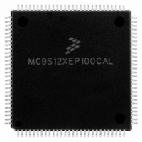
MC9S12XEP100CAL Freescale Semiconductor, MC9S12XEP100CAL Datasheet - Page 710

MC9S12XEP100CAL
Manufacturer Part Number
MC9S12XEP100CAL
Description
IC MCU 16BIT 1M FLASH 112-LQFP
Manufacturer
Freescale Semiconductor
Series
HCS12r
Datasheet
1.MC9S12XEP768CAL.pdf
(1328 pages)
Specifications of MC9S12XEP100CAL
Core Processor
HCS12X
Core Size
16-Bit
Speed
50MHz
Connectivity
CAN, EBI/EMI, I²C, IrDA, SCI, SPI
Peripherals
LVD, POR, PWM, WDT
Number Of I /o
91
Program Memory Size
1MB (1M x 8)
Program Memory Type
FLASH
Eeprom Size
4K x 8
Ram Size
64K x 8
Voltage - Supply (vcc/vdd)
1.72 V ~ 5.5 V
Data Converters
A/D 16x12b
Oscillator Type
External
Operating Temperature
-40°C ~ 85°C
Package / Case
112-LQFP
Processor Series
S12XE
Core
HCS12
Data Bus Width
16 bit
Data Ram Size
64 KB
Interface Type
CAN/SCI/SPI
Maximum Clock Frequency
50 MHz
Number Of Programmable I/os
91
Number Of Timers
25
Maximum Operating Temperature
+ 85 C
Mounting Style
SMD/SMT
3rd Party Development Tools
EWHCS12
Development Tools By Supplier
KIT33812ECUEVME, EVB9S12XEP100, DEMO9S12XEP100
Minimum Operating Temperature
- 40 C
On-chip Adc
16-ch x 12-bit
Package
112LQFP
Family Name
HCS12X
Maximum Speed
50 MHz
Operating Supply Voltage
1.8|2.8|5 V
For Use With
EVB9S12XEP100 - BOARD EVAL FOR MC9S12XEP100DEMO9S12XEP100 - BOARD DEMO FOR MC9S12XEP100
Lead Free Status / RoHS Status
Lead free / RoHS Compliant
Available stocks
Company
Part Number
Manufacturer
Quantity
Price
Company:
Part Number:
MC9S12XEP100CAL
Manufacturer:
TOSHIBA
Quantity:
72
Company:
Part Number:
MC9S12XEP100CAL
Manufacturer:
Freescale Semiconductor
Quantity:
10 000
- Current page: 710 of 1328
- Download datasheet (9Mb)
Chapter 19 Pulse-Width Modulator (S12PWM8B8CV1)
For boundary case programming values, please refer to
Read: Anytime
Write: Anytime
19.3.2.15 PWM Shutdown Register (PWMSDN)
The PWMSDN register provides for the shutdown functionality of the PWM module in the emergency
cases. For proper operation, channel 7 must be driven to the active level for a minimum of two bus clocks.
Read: Anytime
Write: Anytime
710
Module Base + 0x001C = PWMDTY0, 0x001D = PWMDTY1, 0x001E = PWMDTY2, 0x001F = PWMDTY3
Module Base + 0x0020 = PWMDTY4, 0x0021 = PWMDTY5, 0x0022 = PWMDTY6, 0x0023 = PWMDTY7
Module Base + 0x0024
PWMRSTRT
Because of an order from the United States International Trade Commission, BGA-packaged product lines and partnumbers
PWMIF
PWMIE
Reset
Reset
indicated here currently are not available from Freescale for import or sale in the United States prior to September 2010
Field
7
6
5
W
W
R
R
Duty Cycle = [PWMDTYx / PWMPERx] * 100%
PWMIF
Bit 7
PWM Interrupt Flag — Any change from passive to asserted (active) state or from active to passive state will
be flagged by setting the PWMIF flag = 1. The flag is cleared by writing a logic 1 to it. Writing a 0 has no effect.
0 No change on PWM7IN input.
1 Change on PWM7IN input
PWM Interrupt Enable — If interrupt is enabled an interrupt to the CPU is asserted.
0 PWM interrupt is disabled.
1 PWM interrupt is enabled.
PWM Restart — The PWM can only be restarted if the PWM channel input 7 is de-asserted. After writing a logic
1 to the PWMRSTRT bit (trigger event) the PWM channels start running after the corresponding counter passes
next “counter == 0” phase. Also, if the PWM7ENA bit is reset to 0, the PWM do not start before the counter
passes $00. The bit is always read as “0”.
1
0
7
7
= Unimplemented or Reserved
PWMIE
Figure 19-16. PWM Channel Duty Registers (PWMDTYx)
1
0
6
6
6
Figure 19-17. PWM Shutdown Register (PWMSDN)
MC9S12XE-Family Reference Manual , Rev. 1.23
PWMRSTRT
5
1
5
0
0
5
PWMLVL
1
0
4
4
4
Description
Section 19.4.2.8, “PWM Boundary
1
0
0
3
3
3
PWM7IN
2
1
2
0
2
PWM7INL
Freescale Semiconductor
1
0
1
1
1
Cases”.
PWM7ENA
Bit 0
1
0
0
0
Related parts for MC9S12XEP100CAL
Image
Part Number
Description
Manufacturer
Datasheet
Request
R
Part Number:
Description:
Manufacturer:
Freescale Semiconductor, Inc
Datasheet:
Part Number:
Description:
Manufacturer:
Freescale Semiconductor, Inc
Datasheet:
Part Number:
Description:
Manufacturer:
Freescale Semiconductor, Inc
Datasheet:
Part Number:
Description:
Manufacturer:
Freescale Semiconductor, Inc
Datasheet:
Part Number:
Description:
Manufacturer:
Freescale Semiconductor, Inc
Datasheet:
Part Number:
Description:
Manufacturer:
Freescale Semiconductor, Inc
Datasheet:
Part Number:
Description:
Manufacturer:
Freescale Semiconductor, Inc
Datasheet:
Part Number:
Description:
Manufacturer:
Freescale Semiconductor, Inc
Datasheet:
Part Number:
Description:
Manufacturer:
Freescale Semiconductor, Inc
Datasheet:
Part Number:
Description:
Manufacturer:
Freescale Semiconductor, Inc
Datasheet:
Part Number:
Description:
Manufacturer:
Freescale Semiconductor, Inc
Datasheet:
Part Number:
Description:
Manufacturer:
Freescale Semiconductor, Inc
Datasheet:
Part Number:
Description:
Manufacturer:
Freescale Semiconductor, Inc
Datasheet:
Part Number:
Description:
Manufacturer:
Freescale Semiconductor, Inc
Datasheet:
Part Number:
Description:
Manufacturer:
Freescale Semiconductor, Inc
Datasheet:


