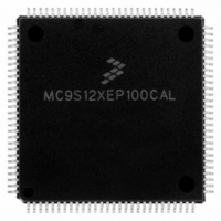
MC9S12XEP100CAL Freescale Semiconductor, MC9S12XEP100CAL Datasheet - Page 78

MC9S12XEP100CAL
Manufacturer Part Number
MC9S12XEP100CAL
Description
IC MCU 16BIT 1M FLASH 112-LQFP
Manufacturer
Freescale Semiconductor
Series
HCS12r
Datasheet
1.MC9S12XEP768CAL.pdf
(1328 pages)
Specifications of MC9S12XEP100CAL
Core Processor
HCS12X
Core Size
16-Bit
Speed
50MHz
Connectivity
CAN, EBI/EMI, I²C, IrDA, SCI, SPI
Peripherals
LVD, POR, PWM, WDT
Number Of I /o
91
Program Memory Size
1MB (1M x 8)
Program Memory Type
FLASH
Eeprom Size
4K x 8
Ram Size
64K x 8
Voltage - Supply (vcc/vdd)
1.72 V ~ 5.5 V
Data Converters
A/D 16x12b
Oscillator Type
External
Operating Temperature
-40°C ~ 85°C
Package / Case
112-LQFP
Processor Series
S12XE
Core
HCS12
Data Bus Width
16 bit
Data Ram Size
64 KB
Interface Type
CAN/SCI/SPI
Maximum Clock Frequency
50 MHz
Number Of Programmable I/os
91
Number Of Timers
25
Maximum Operating Temperature
+ 85 C
Mounting Style
SMD/SMT
3rd Party Development Tools
EWHCS12
Development Tools By Supplier
KIT33812ECUEVME, EVB9S12XEP100, DEMO9S12XEP100
Minimum Operating Temperature
- 40 C
On-chip Adc
16-ch x 12-bit
Package
112LQFP
Family Name
HCS12X
Maximum Speed
50 MHz
Operating Supply Voltage
1.8|2.8|5 V
For Use With
EVB9S12XEP100 - BOARD EVAL FOR MC9S12XEP100DEMO9S12XEP100 - BOARD DEMO FOR MC9S12XEP100
Lead Free Status / RoHS Status
Lead free / RoHS Compliant
Available stocks
Company
Part Number
Manufacturer
Quantity
Price
Company:
Part Number:
MC9S12XEP100CAL
Manufacturer:
TOSHIBA
Quantity:
72
Company:
Part Number:
MC9S12XEP100CAL
Manufacturer:
Freescale Semiconductor
Quantity:
10 000
- Current page: 78 of 1328
- Download datasheet (9Mb)
Chapter 1 Device Overview MC9S12XE-Family
1.4.1.5
Developers use this mode for emulation systems in which the user’s target application is normal single-
chip mode. Code is executed from external memory or from internal memory depending on the state of
ROMON and EROMON bit. In this mode the internal operation is visible on external bus interface.
1.4.1.6
This is for Freescale internal use only.
1.4.2
The MCU features two main low-power modes. Consult the respective module description for module
specific behavior in system stop, system pseudo stop, and system wait mode. An important source of
information about the clock system is the Clock and Reset Generator description (CRG).
1.4.2.1
The system stop modes are entered if the CPU executes the STOP instruction unless either the XGATE is
active or an NVM command is active. The XGATE is active if it executes a thread or the XGFACT bit in
the XGMCTL register is set. Depending on the state of the PSTP bit in the CLKSEL register the MCU
goes into pseudo stop mode or full stop mode. Please refer to CRG description. Asserting RESET, XIRQ,
IRQ or any other interrupt that is not masked exits system stop modes. System stop modes can be exited
by XGATE or CPU activity independently, depending on the configuration of the interrupt request. If
System-Stop is exited on an XGATE request then, as long as the XGATE does not set an interrupt flag on
the CPU and the XGATE fake activity bit (FACT) remains cleared, once XGATE activity is completed
System Stop mode will automatically be re-entered.
If the CPU executes the STOP instruction whilst XGATE is active or an NVM command is being
processed, then the system clocks continue running until XGATE/NVM activity is completed. If a non-
masked interrupt occurs within this time then the system does not effectively enter stop mode although the
STOP instruction has been executed.
1.4.2.2
The oscillator is stopped in this mode. By default all clocks are switched off and all counters and dividers
remain frozen. The Autonomous Periodic Interrupt (API) and ATD modules may be enabled to self wake
the device. A Fast wake up mode is available to allow the device to wake from Full Stop mode immediately
on the PLL internal clock without starting the oscillator clock.
1.4.2.3
In this mode the system clocks are stopped but the oscillator is still running and the real time interrupt
(RTI) and watchdog (COP), API and ATD modules may be enabled. Other peripherals are turned off. This
mode consumes more current than system stop mode but, as the oscillator continues to run, the full speed
wake up time from this mode is significantly shorter.
78
Because of an order from the United States International Trade Commission, BGA-packaged product lines and partnumbers
indicated here currently are not available from Freescale for import or sale in the United States prior to September 2010
Power Modes
Emulation of Single-Chip Mode
Special Test Mode
System Stop Modes
Full Stop Mode
Pseudo Stop Mode
MC9S12XE-Family Reference Manual , Rev. 1.23
Freescale Semiconductor
Related parts for MC9S12XEP100CAL
Image
Part Number
Description
Manufacturer
Datasheet
Request
R
Part Number:
Description:
Manufacturer:
Freescale Semiconductor, Inc
Datasheet:
Part Number:
Description:
Manufacturer:
Freescale Semiconductor, Inc
Datasheet:
Part Number:
Description:
Manufacturer:
Freescale Semiconductor, Inc
Datasheet:
Part Number:
Description:
Manufacturer:
Freescale Semiconductor, Inc
Datasheet:
Part Number:
Description:
Manufacturer:
Freescale Semiconductor, Inc
Datasheet:
Part Number:
Description:
Manufacturer:
Freescale Semiconductor, Inc
Datasheet:
Part Number:
Description:
Manufacturer:
Freescale Semiconductor, Inc
Datasheet:
Part Number:
Description:
Manufacturer:
Freescale Semiconductor, Inc
Datasheet:
Part Number:
Description:
Manufacturer:
Freescale Semiconductor, Inc
Datasheet:
Part Number:
Description:
Manufacturer:
Freescale Semiconductor, Inc
Datasheet:
Part Number:
Description:
Manufacturer:
Freescale Semiconductor, Inc
Datasheet:
Part Number:
Description:
Manufacturer:
Freescale Semiconductor, Inc
Datasheet:
Part Number:
Description:
Manufacturer:
Freescale Semiconductor, Inc
Datasheet:
Part Number:
Description:
Manufacturer:
Freescale Semiconductor, Inc
Datasheet:
Part Number:
Description:
Manufacturer:
Freescale Semiconductor, Inc
Datasheet:


