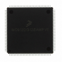
MC912DG128AMPVE Freescale Semiconductor, MC912DG128AMPVE Datasheet - Page 144

MC912DG128AMPVE
Manufacturer Part Number
MC912DG128AMPVE
Description
IC MCU 128K FLASH 8MHZ 112-LQFP
Manufacturer
Freescale Semiconductor
Series
HC12r
Datasheet
1.MC912DG128ACPVER.pdf
(478 pages)
Specifications of MC912DG128AMPVE
Core Processor
CPU12
Core Size
16-Bit
Speed
8MHz
Connectivity
CAN, I²C, SCI, SPI
Peripherals
POR, PWM, WDT
Number Of I /o
69
Program Memory Size
128KB (128K x 8)
Program Memory Type
FLASH
Eeprom Size
2K x 8
Ram Size
8K x 8
Voltage - Supply (vcc/vdd)
4.5 V ~ 5.5 V
Data Converters
A/D 16x8/10b
Oscillator Type
Internal
Operating Temperature
-40°C ~ 125°C
Package / Case
112-LQFP
Processor Series
HC912D
Core
HC12
Data Bus Width
16 bit
Data Ram Size
8 KB
Interface Type
CAN/I2C/SCI/SPI
Maximum Clock Frequency
8 MHz
Number Of Programmable I/os
69
Number Of Timers
8
Maximum Operating Temperature
+ 125 C
Mounting Style
SMD/SMT
3rd Party Development Tools
EWHCS12
Minimum Operating Temperature
- 40 C
On-chip Adc
2 (8-ch x 10-bit)
Lead Free Status / RoHS Status
Lead free / RoHS Compliant
Available stocks
Company
Part Number
Manufacturer
Quantity
Price
Company:
Part Number:
MC912DG128AMPVE
Manufacturer:
FREESCALE
Quantity:
2 902
Company:
Part Number:
MC912DG128AMPVE
Manufacturer:
Freescale Semiconductor
Quantity:
10 000
- Current page: 144 of 478
- Download datasheet (4Mb)
Resets and Interrupts
10.8.2 External Reset
10.8.3 COP Reset
Technical Data
144
source of reset in a system. The POR circuit only initializes internal
circuitry during cold starts and cannot be used to force a reset as system
voltage drops.
It is important to use an external low voltage reset circuit (for example:
MC34064 or MC33464) to prevent power transitions or corruption of
RAM or EEPROM.
The CPU distinguishes between internal and external reset conditions
by sensing whether the reset pin rises to a logic one in less than nine E-
clock cycles after an internal device releases reset. When a reset
condition is sensed, an internal circuit drives the RESET pin low and a
clocked reset sequence controls when the MCU can begin normal
processing. In the case of a clock monitor error, a 4096 cycle oscillator
start-up delay is imposed before the reset recovery sequence starts
(reset is driven low throughout this 4096 cycle delay). The internal reset
recovery sequence then drives reset low for 16 to 17 cycles and releases
the drive to allow reset to rise. Nine E-clock cycles later the reset pin is
sampled. If the pin is still held low, the CPU assumes that an external
reset has occurred. If the pin is high, it indicates that the reset was
initiated internally by either the COP system or the clock monitor.
To prevent a COP reset from being detected during an external reset,
hold the reset pin low for at least 32 cycles. To prevent a clock monitor
reset from being detected during an external reset, hold the reset pin low
for at least 4096 + 32 cycles. An external RC power-up delay circuit on
the reset pin is not recommended — circuit charge time can cause the
MCU to misinterpret the type of reset that has occurred.
The MCU includes a computer operating properly (COP) system to help
protect against software failures. When COP is enabled, software must
write $55 and $AA (in this order) to the COPRST register in order to keep
a watchdog timer from timing out. Other instructions may be executed
between these writes. A write of any value other than $55 or $AA or
Freescale Semiconductor, Inc.
For More Information On This Product,
Go to: www.freescale.com
Resets and Interrupts
MC68HC912DT128A — Rev 4.0
MOTOROLA
Related parts for MC912DG128AMPVE
Image
Part Number
Description
Manufacturer
Datasheet
Request
R
Part Number:
Description:
Manufacturer:
Freescale Semiconductor, Inc
Datasheet:
Part Number:
Description:
Manufacturer:
Freescale Semiconductor, Inc
Datasheet:
Part Number:
Description:
Manufacturer:
Freescale Semiconductor, Inc
Datasheet:
Part Number:
Description:
Manufacturer:
Freescale Semiconductor, Inc
Datasheet:
Part Number:
Description:
Manufacturer:
Freescale Semiconductor, Inc
Datasheet:
Part Number:
Description:
Manufacturer:
Freescale Semiconductor, Inc
Datasheet:
Part Number:
Description:
Manufacturer:
Freescale Semiconductor, Inc
Datasheet:
Part Number:
Description:
Manufacturer:
Freescale Semiconductor, Inc
Datasheet:
Part Number:
Description:
Manufacturer:
Freescale Semiconductor, Inc
Datasheet:
Part Number:
Description:
Manufacturer:
Freescale Semiconductor, Inc
Datasheet:
Part Number:
Description:
Manufacturer:
Freescale Semiconductor, Inc
Datasheet:
Part Number:
Description:
Manufacturer:
Freescale Semiconductor, Inc
Datasheet:
Part Number:
Description:
Manufacturer:
Freescale Semiconductor, Inc
Datasheet:
Part Number:
Description:
Manufacturer:
Freescale Semiconductor, Inc
Datasheet:
Part Number:
Description:
Manufacturer:
Freescale Semiconductor, Inc
Datasheet:


