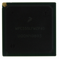
MPC555LFMZP40 Freescale Semiconductor, MPC555LFMZP40 Datasheet - Page 213

MPC555LFMZP40
Manufacturer Part Number
MPC555LFMZP40
Description
IC MCU 32BIT 40MHZ 272-BGA
Manufacturer
Freescale Semiconductor
Series
MPC5xxr
Datasheets
1.MPC555LFMZP40.pdf
(12 pages)
2.MPC555LFMZP40.pdf
(966 pages)
3.MPC555LFMZP40.pdf
(3 pages)
Specifications of MPC555LFMZP40
Core Processor
PowerPC
Core Size
32-Bit
Speed
40MHz
Connectivity
CAN, EBI/EMI, SCI, SPI, UART/USART
Peripherals
POR, PWM, WDT
Number Of I /o
101
Program Memory Size
448KB (448K x 8)
Program Memory Type
FLASH
Ram Size
26K x 8
Voltage - Supply (vcc/vdd)
2.5 V ~ 2.7 V
Data Converters
A/D 32x10b
Oscillator Type
External
Operating Temperature
-40°C ~ 125°C
Package / Case
272-PBGA
Controller Family/series
POWER 5xx
Ram Memory Size
26KB
Cpu Speed
63MIPS
Embedded Interface Type
QSPI, SCI, TouCAN
Operating Temperature Range
-40°C To +125°C
No. Of Pins
272
Rohs Compliant
No
Processor Series
MPC5xx
Core
PowerPC
Data Bus Width
32 bit
Data Ram Size
26 KB
Interface Type
CAN, QSPI, SCI
Maximum Clock Frequency
40 MHz
Number Of Programmable I/os
101
Operating Supply Voltage
3.3 V to 5 V
Maximum Operating Temperature
+ 125 C
Mounting Style
SMD/SMT
Development Tools By Supplier
MPC555CMEE
Minimum Operating Temperature
- 85 C
On-chip Adc
10 bit, 32 Channel
Cpu Family
MPC55xx
Device Core
PowerPC
Device Core Size
32b
Frequency (max)
40MHz
Total Internal Ram Size
32KB
# I/os (max)
101
Operating Supply Voltage (typ)
5V
Instruction Set Architecture
RISC
Operating Temp Range
-40C to 85C
Operating Temperature Classification
Industrial
Mounting
Surface Mount
Pin Count
272
Package Type
BGA
For Use With
MPC555CMEE - KIT EVAL FOR MPC555
Lead Free Status / RoHS Status
Contains lead / RoHS non-compliant
Eeprom Size
-
Lead Free Status / Rohs Status
No
Available stocks
Company
Part Number
Manufacturer
Quantity
Price
Company:
Part Number:
MPC555LFMZP40
Manufacturer:
MOTOLOLA
Quantity:
853
Company:
Part Number:
MPC555LFMZP40
Manufacturer:
Freescale Semiconductor
Quantity:
10 000
Company:
Part Number:
MPC555LFMZP40R2
Manufacturer:
Freescale Semiconductor
Quantity:
10 000
- Current page: 213 of 966
- Download datasheet (15Mb)
6.2 External Master Modes
6.2.1 Operation of External Master Modes
MPC555
USER’S MANUAL
External master modes are special modes of operation that allow an alternate master
on the external bus to access the internal modules for debugging and backup purpos-
es. They provide access to the internal buses (U-bus and L-bus) and to the intermod-
ule bus (IMB3).
There are two external master modes. Peripheral mode (enabled by setting PRPM in
the EMCR) is a special slave mechanism in which the RCPU is shut down and an al-
ternate master on the external bus can perform accesses to any internal bus slave.
Slave mode (enabled by setting SLVM and clearing PRPM in the EMCR) enables an
external master to access any internal bus slave while the RCPU is fully operational.
Both modes can be enabled and disabled by software. In addition, peripheral mode
can be selected from reset.
The internal bus is not capable of providing fair priority between internal RCPU ac-
cesses and external master accesses. If the bandwidth of external master accesses is
large, it is recommended that the system forces gaps between external master ac-
cesses in order to avoid suspension of internal RCPU activity.
The MPC555 / MPC556 does not support burst accesses from an external master;
only single accesses of 8, 16, or 32 bits can be performed. The MPC555 / MPC556
asserts burst inhibit (BI) on any attempt to initiate a burst access to internal memory.
The MPC555 / MPC556 provides memory controller services for external master ac-
cesses (single and burst) to external memories. See
TROLLER
The external master modes are controlled by the EMCR register, which contains the
internal bus attributes. The default attributes in the EMCR enable the external master
to configure EMCR with the required attributes, and then access the internal registers.
The external master must be granted external bus ownership in order to initiate the ex-
ternal master access. The SIU compares the address on the external bus to the allo-
cated internal address space. If the address is within the internal space, the access is
performed with the internal bus. The internal address space is determined according
to ISB (see
access is terminated by the TA, TEA or RETRY signal on the external bus.
A deadlock situation might occur if an internal-to-external access is attempted on the
internal bus while an external master access is initiated on the external bus. In this
case, the SIU will assert the RETRY on the external bus in order to relinquish and retry
the external access until the internal access is completed. The internal bus will deny
other internal accesses for the next eight clocks in order to complete the pending ac-
cesses and prevent additional internal accesses from being initiated on the internal
bus. The SIU will also mask internal accesses to support consecutive external access-
es if the delay between the external accesses is less than 4 clocks. The external mas-
ter access and retry timings are described in
Master
/
MPC556
Modes.
for details.
6.13.1.2 Internal Memory Map Register
Freescale Semiconductor, Inc.
SYSTEM CONFIGURATION AND PROTECTION
For More Information On This Product,
Go to: www.freescale.com
Rev. 15 October 2000
9.5.11 Bus Operation in External
for details). The external master
SECTION 10 MEMORY CON-
MOTOROLA
6-5
Related parts for MPC555LFMZP40
Image
Part Number
Description
Manufacturer
Datasheet
Request
R
Part Number:
Description:
Manufacturer:
Freescale Semiconductor, Inc
Datasheet:
Part Number:
Description:
Manufacturer:
Freescale Semiconductor, Inc
Datasheet:
Part Number:
Description:
Manufacturer:
Freescale Semiconductor, Inc
Datasheet:
Part Number:
Description:
Manufacturer:
Freescale Semiconductor, Inc
Datasheet:
Part Number:
Description:
Manufacturer:
Freescale Semiconductor, Inc
Datasheet:
Part Number:
Description:
Manufacturer:
Freescale Semiconductor, Inc
Datasheet:
Part Number:
Description:
Manufacturer:
Freescale Semiconductor, Inc
Datasheet:
Part Number:
Description:
Manufacturer:
Freescale Semiconductor, Inc
Datasheet:
Part Number:
Description:
Manufacturer:
Freescale Semiconductor, Inc
Datasheet:
Part Number:
Description:
Manufacturer:
Freescale Semiconductor, Inc
Datasheet:
Part Number:
Description:
Manufacturer:
Freescale Semiconductor, Inc
Datasheet:
Part Number:
Description:
Manufacturer:
Freescale Semiconductor, Inc
Datasheet:
Part Number:
Description:
Manufacturer:
Freescale Semiconductor, Inc
Datasheet:
Part Number:
Description:
Manufacturer:
Freescale Semiconductor, Inc
Datasheet:
Part Number:
Description:
Manufacturer:
Freescale Semiconductor, Inc
Datasheet:


