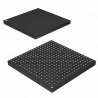
AT91SAM9M10-CU Atmel, AT91SAM9M10-CU Datasheet - Page 1158

AT91SAM9M10-CU
Manufacturer Part Number
AT91SAM9M10-CU
Description
IC MCU 16/32BIT ARM9 324TFBGA
Manufacturer
Atmel
Series
AT91SAMr
Specifications of AT91SAM9M10-CU
Core Processor
ARM9
Core Size
16/32-Bit
Speed
400MHz
Connectivity
EBI/EMI, Ethernet, I²C, SPI, SSC, UART/USART, USB
Peripherals
AC'97, DMA, LCD, POR, PWM, WDT
Number Of I /o
160
Program Memory Size
64KB (64K x 8)
Program Memory Type
ROM
Ram Size
128K x 8
Voltage - Supply (vcc/vdd)
0.9 V ~ 1.1 V
Data Converters
A/D 8x10b
Oscillator Type
Internal
Operating Temperature
-40°C ~ 85°C
Package / Case
324-TFBGA
Processor Series
AT91SAMx
Core
ARM926EJ-S
Data Bus Width
32 bit
Data Ram Size
32 KB
Interface Type
2-Wire, SPI, USART
Maximum Clock Frequency
133 MHz
Number Of Programmable I/os
5
Number Of Timers
2 x 16 bit
Operating Supply Voltage
1.65 V to 3.6 V
Maximum Operating Temperature
+ 85 C
Mounting Style
SMD/SMT
3rd Party Development Tools
JTRACE-ARM-2M, MDK-ARM, RL-ARM, ULINK2
Development Tools By Supplier
AT91SAM-ICE, AT91-ISP, AT91SAM9M10-G45-EK
Controller Family/series
AT91
No. Of I/o's
160
Ram Memory Size
64KB
Cpu Speed
400MHz
No. Of Timers
2
Rohs Compliant
Yes
Cpu Family
AT91
Device Core
ARM926EJ-S
Device Core Size
32b
Frequency (max)
400MHz
Total Internal Ram Size
64KB
# I/os (max)
160
Number Of Timers - General Purpose
7
Operating Supply Voltage (typ)
1.8/2.5/3.3V
Operating Supply Voltage (max)
1.1/1.95/3.6V
Operating Supply Voltage (min)
0.9/1.65/1.8/3V
On-chip Adc
8-chx10-bit
Instruction Set Architecture
RISC
Operating Temp Range
-40C to 85C
Operating Temperature Classification
Industrial
Mounting
Surface Mount
Pin Count
324
Package Type
TFBGA
Lead Free Status / RoHS Status
Lead free / RoHS Compliant
Eeprom Size
-
Lead Free Status / Rohs Status
Lead free / RoHS Compliant
Available stocks
Company
Part Number
Manufacturer
Quantity
Price
Company:
Part Number:
AT91SAM9M10-CU
Manufacturer:
Atmel
Quantity:
996
- Current page: 1158 of 1404
- Download datasheet (22Mb)
46.3.2
6355B–ATARM–21-Jun-10
Decoder Data Flow, Hardware Performs Entropy Decoding (VLC Mode)
Table 46-6.
Notes:
The decoder software starts decoding the first picture by parsing the stream headers (1). Soft-
ware then setups the hardware control registers (picture size, stream start address etc.) and
enables the hardware (2).
In JPEG case, software parses VLC and QP tables from the stream and writes them to a contig-
uous memory area. In VC-1 case, software parses bitplane macroblock control from the stream
and writes it to memory.
Hardware decodes the picture by reading stream, VLC and QP tables for JPEG (3), and the ref-
erence pictures (4) (required for inter picture decoding) from the external memory. Hardware
writes the decoded output picture to memory (5) one macroblock at a time. When the picture has
been fully decoded, or the hardware has run out of stream data, it gives an interrupt with a
proper status flag and provides stream end address for software to continue and returns to initial
state.
In case the hardware detects erroneous stream during decoding, it will return an error interrupt,
and software will start concealing errors for the current picture. Depending on the selected con-
cealment method, software may re-initialize the hardware in the SW entropy decode mode. The
pictures following the corrupted one are decoded in the normal mode until the next error is
detected.
If post-processing is enabled, one or two additional image transfer operations will take place. If
the decoded images are in display order (i.e. no picture re-ordering has been made when
encoding the sequence), and rotation is not used, PP will process the pictures in pipeline with
the decoder. Otherwise, it will first have to read the decoded image that is to be displayed next
from the memory (6), and then write back the processed image (7).
RGB image color saturation
adjustment
De-blocking filter for MPEG-
4 simple profile/H.263
Image cropping /digital
zoom
Picture in picture
Supported display size for
picture in picture
Output image masking
Image rotation
1. Step size in the start and end coordinates depends on the output picture format and the width
2. Usable in stand-alone post-processing mode only.
of the data bus.
(2)
Postprocessing Features (Continued)
Linear
Using a modified H.264 in-loop filter as a post-processing filter. Filtering
has to be performed in combined mode.
User definable start position, height and width. Can be used with scaling to
perform digital zoom. Usable only for JPEG or standalone mode.
Output image can be written to any location inside video memory
Up to 1280 x 720
Output image writing can be prevented on two rectangular areas in the
image
is possible to have one masking area and one blending area.
Rotation 90, 180 or 270 degrees
Horizontal flip
Vertical flip
(1)
. The masking feature is exclusive with alpha blending however it
AT91SAM9M10
(1)
1158
Related parts for AT91SAM9M10-CU
Image
Part Number
Description
Manufacturer
Datasheet
Request
R

Part Number:
Description:
MCU, MPU & DSP Development Tools KICKSTART KIT FOR AT91SAM9 PLUS
Manufacturer:
IAR Systems

Part Number:
Description:
DEV KIT FOR AVR/AVR32
Manufacturer:
Atmel
Datasheet:

Part Number:
Description:
INTERVAL AND WIPE/WASH WIPER CONTROL IC WITH DELAY
Manufacturer:
ATMEL Corporation
Datasheet:

Part Number:
Description:
Low-Voltage Voice-Switched IC for Hands-Free Operation
Manufacturer:
ATMEL Corporation
Datasheet:

Part Number:
Description:
MONOLITHIC INTEGRATED FEATUREPHONE CIRCUIT
Manufacturer:
ATMEL Corporation
Datasheet:

Part Number:
Description:
AM-FM Receiver IC U4255BM-M
Manufacturer:
ATMEL Corporation
Datasheet:

Part Number:
Description:
Monolithic Integrated Feature Phone Circuit
Manufacturer:
ATMEL Corporation
Datasheet:

Part Number:
Description:
Multistandard Video-IF and Quasi Parallel Sound Processing
Manufacturer:
ATMEL Corporation
Datasheet:

Part Number:
Description:
High-performance EE PLD
Manufacturer:
ATMEL Corporation
Datasheet:

Part Number:
Description:
8-bit Flash Microcontroller
Manufacturer:
ATMEL Corporation
Datasheet:

Part Number:
Description:
2-Wire Serial EEPROM
Manufacturer:
ATMEL Corporation
Datasheet:


