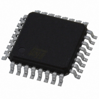
ST72F32AK2T6 STMicroelectronics, ST72F32AK2T6 Datasheet - Page 154

ST72F32AK2T6
Manufacturer Part Number
ST72F32AK2T6
Description
MCU 8BIT 8KB FLASH/ROM 32-TQFP
Manufacturer
STMicroelectronics
Series
ST7r
Datasheet
1.ST72F32AK2T6.pdf
(157 pages)
Specifications of ST72F32AK2T6
Core Processor
ST7
Core Size
8-Bit
Speed
8MHz
Connectivity
SCI, SPI
Peripherals
POR, PWM, WDT
Number Of I /o
24
Program Memory Size
8KB (8K x 8)
Program Memory Type
FLASH
Ram Size
384 x 8
Voltage - Supply (vcc/vdd)
3.8 V ~ 5.5 V
Data Converters
A/D 12x10b
Oscillator Type
External
Operating Temperature
-40°C ~ 85°C
Package / Case
32-TQFP, 32-VQFP
Processor Series
ST72F3x
Core
ST7
Data Bus Width
8 bit
Data Ram Size
384 B
Interface Type
SCI, SPI
Maximum Clock Frequency
8 MHz
Number Of Programmable I/os
32
Number Of Timers
3
Maximum Operating Temperature
+ 85 C
Mounting Style
SMD/SMT
Development Tools By Supplier
ST7232X-EVAL, ST7MDT20-DVP3, ST7MDT20J-EMU3, STX-RLINK
Minimum Operating Temperature
- 40 C
On-chip Adc
10 bit, 12 Channel
A/d Bit Size
10 bit
A/d Channels Available
12
Height
1.4 mm
Length
7 mm
Supply Voltage (max)
5.5 V
Supply Voltage (min)
3.8 V
Width
7 mm
For Use With
497-5046 - KIT TOOL FOR ST7/UPSD/STR7 MCU
Lead Free Status / RoHS Status
Lead free / RoHS Compliant
Eeprom Size
-
Lead Free Status / Rohs Status
Details
Other names
497-5610
Available stocks
Company
Part Number
Manufacturer
Quantity
Price
Company:
Part Number:
ST72F32AK2T6
Manufacturer:
STMicroelectronics
Quantity:
10 000
ST7232A
15 KNOWN LIMITATIONS
15.1 ALL FLASH AND ROM DEVICES
15.1.1 Safe Connection of OSC1/OSC2 Pins
The OSC1 and/or OSC2 pins must not be left un-
connected otherwise the ST7 main oscillator may
start and, in this configuration, could generate an
f
maximum (>16MHz.), putting the ST7 in an un-
safe/undefined state. Refer to
24.
15.1.2 Unexpected Reset Fetch
If an interrupt request occurs while a "POP CC" in-
struction is executed, the interrupt controller does
not recognise the source of the interrupt and, by
default, passes the RESET vector address to the
CPU.
Workaround
To solve this issue, a "POP CC" instruction must
always be preceded by a "SIM" instruction.
15.1.3
interrupt routine
When an active interrupt request occurs at the
same time as the related flag is being cleared, an
unwanted reset may occur.
Note: clearing the related interrupt mask will not
generate an unwanted reset
Concurrent interrupt context
The symptom does not occur when the interrupts
are handled normally, i.e.
when:
– The interrupt flag is cleared within its own inter-
– The interrupt flag is cleared within any interrupt
– The interrupt flag is cleared in any part of the
If these conditions are not met, the symptom can
be avoided by implementing the following se-
quence:
Perform SIM and RIM operation before and after
resetting an active interrupt request.
Example:
154/157
1
OSC
rupt routine
routine
code while this interrupt is disabled
SIM
reset interrupt flag
RIM
clock frequency in excess of the allowed
Clearing
active
interrupts
Section 6.2 on page
outside
Nested interrupt context:
The symptom does not occur when the interrupts
are handled normally, i.e.
when:
– The interrupt flag is cleared within its own inter-
– The interrupt flag is cleared within any interrupt
– The interrupt flag is cleared in any part of the
If these conditions are not met, the symptom can
be avoided by implementing the following se-
quence:
15.1.4 16-bit Timer PWM Mode
In PWM mode, the first PWM pulse is missed after
writing the value FFFCh in the OC1R register
(OC1HR, OC1LR). It leads to either full or no PWM
during a period, depending on the OLVL1 and
OLVL2 settings.
15.1.5 SCI Wrong Break duration
Description
A single break character is sent by setting and re-
setting the SBK bit in the SCICR2 register. In
some cases, the break character may have a long-
er duration than expected:
- 20 bits instead of 10 bits if M=0
- 22 bits instead of 11 bits if M=1.
In the same way, as long as the SBK bit is set,
break characters are sent to the TDO pin. This
may lead to generate one break more than expect-
ed.
Occurrence
The occurrence of the problem is random and pro-
portional to the baudrate. With a transmit frequen-
cy of 19200 baud (fCPU=8MHz and SCI-
BRR=0xC9), the wrong break duration occurrence
is around 1%.
Workaround
If this wrong duration is not compliant with the
communication protocol in the application, soft-
ware can request that an Idle line be generated
before the break character. In this case, the break
duration is always correct assuming the applica-
rupt routine
routine with higher or identical priority level
code while this interrupt is disabled
PUSH CC
SIM
reset interrupt flag
POP CC


