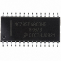
MC705P6ACDWE Freescale Semiconductor, MC705P6ACDWE Datasheet - Page 49

MC705P6ACDWE
Manufacturer Part Number
MC705P6ACDWE
Description
IC MCU 176 BYTES RAM 28-SOIC
Manufacturer
Freescale Semiconductor
Series
HC05r
Datasheet
1.MC705P6ACDWE.pdf
(98 pages)
Specifications of MC705P6ACDWE
Core Processor
HC05
Core Size
8-Bit
Speed
2.1MHz
Connectivity
SIO
Peripherals
POR, WDT
Number Of I /o
21
Program Memory Size
4.5KB (4.5K x 8)
Program Memory Type
OTP
Ram Size
176 x 8
Voltage - Supply (vcc/vdd)
3 V ~ 5.5 V
Data Converters
A/D 4x8b
Oscillator Type
Internal
Operating Temperature
-40°C ~ 85°C
Package / Case
28-SOIC (7.5mm Width)
Processor Series
HC705P
Core
HC05
Data Bus Width
8 bit
Data Ram Size
176 B
Maximum Clock Frequency
2.1 MHz
Number Of Programmable I/os
21
Number Of Timers
1
Maximum Operating Temperature
+ 85 C
Mounting Style
SMD/SMT
Minimum Operating Temperature
- 40 C
On-chip Adc
8 bit, 4 Channel
Lead Free Status / RoHS Status
Lead free / RoHS Compliant
Eeprom Size
-
Lead Free Status / Rohs Status
Details
Available stocks
Company
Part Number
Manufacturer
Quantity
Price
Company:
Part Number:
MC705P6ACDWE
Manufacturer:
Freescale Semiconductor
Quantity:
135
Part Number:
MC705P6ACDWE
Manufacturer:
FREESCALE
Quantity:
20 000
8.3.3 Timer Registers
The timer registers (TRH and TRL), shown in
16-bit counter. Reading TRH before reading TRL causes TRL to be latched until TRL is read. Reading
TRL after reading the timer status register clears the timer overflow flag (TOF). Writing to the timer
registers has no effect.
8.3.4 Alternate Timer Registers
The alternate timer registers (ATRH and ATRL), shown in
bytes of the 16-bit counter. Reading ATRH before reading ATRL causes ATRL to be latched until ATRL
is read. Reading ATRL has no effect on the timer overflow flag (TOF). Writing to the alternate timer
registers has no effect.
Freescale Semiconductor
Address:
Address:
Address:
Address:
To prevent interrupts from occurring between readings of ATRH and ATRL,
set the interrupt flag in the condition code register before reading ATRH,
and clear the flag after reading ATRL.
Reset:
Reset:
Reset:
Reset:
Read:
Read:
Write:
Write:
Write:
Write
Figure 8-5. Alternate Timer Registers (ATRH and ATRL)
TRH — $0018
TRL — $0019
ATRH — $001A
ATRL — $001B
ACRH7
TRH7
Bit 7
Bit 7
Bit 7
Bit 7
1
1
1
1
MC68HC705P6A Advance Information Data Sheet, Rev. 2.1
Figure 8-4. Timer Registers (TRH and TRL)
= Unimplemented
= Unimplemented
ACRH6
TRH6
6
1
6
1
6
1
6
1
ACRH5
TRH5
5
1
5
1
5
1
5
1
Figure
NOTE
ACRH4
TRH4
4
1
4
1
4
1
4
1
8-4, contains the current high and low bytes of the
Figure
ACRH3
TRH3
3
1
3
1
3
1
3
1
8-5, contain the current high and low
ACRH2
TRH2
2
1
2
1
2
1
2
1
ACRH1
TRH1
1
1
1
0
1
1
1
0
ACRH0
TRH0
Bit 0
Bit 0
Bit 0
Bit 0
Timer I/O Registers
1
0
1
0
49


