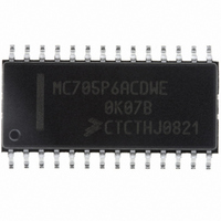
MC705P6ACDWE Freescale Semiconductor, MC705P6ACDWE Datasheet - Page 53

MC705P6ACDWE
Manufacturer Part Number
MC705P6ACDWE
Description
IC MCU 176 BYTES RAM 28-SOIC
Manufacturer
Freescale Semiconductor
Series
HC05r
Datasheet
1.MC705P6ACDWE.pdf
(98 pages)
Specifications of MC705P6ACDWE
Core Processor
HC05
Core Size
8-Bit
Speed
2.1MHz
Connectivity
SIO
Peripherals
POR, WDT
Number Of I /o
21
Program Memory Size
4.5KB (4.5K x 8)
Program Memory Type
OTP
Ram Size
176 x 8
Voltage - Supply (vcc/vdd)
3 V ~ 5.5 V
Data Converters
A/D 4x8b
Oscillator Type
Internal
Operating Temperature
-40°C ~ 85°C
Package / Case
28-SOIC (7.5mm Width)
Processor Series
HC705P
Core
HC05
Data Bus Width
8 bit
Data Ram Size
176 B
Maximum Clock Frequency
2.1 MHz
Number Of Programmable I/os
21
Number Of Timers
1
Maximum Operating Temperature
+ 85 C
Mounting Style
SMD/SMT
Minimum Operating Temperature
- 40 C
On-chip Adc
8 bit, 4 Channel
Lead Free Status / RoHS Status
Lead free / RoHS Compliant
Eeprom Size
-
Lead Free Status / Rohs Status
Details
Available stocks
Company
Part Number
Manufacturer
Quantity
Price
Company:
Part Number:
MC705P6ACDWE
Manufacturer:
Freescale Semiconductor
Quantity:
135
Part Number:
MC705P6ACDWE
Manufacturer:
FREESCALE
Quantity:
20 000
Chapter 9
Analog Subsystem
9.1 Introduction
The MC68HC705P6A includes a 4-channel, multiplexed input, 8-bit, successive approximation
analog-to-digital (A/D) converter. The A/D subsystem shares its inputs with port C pins PC3–PC7.
9.2 Analog Section
The following paragraphs describe the operation and performance of analog modules within the analog
subsystem.
9.2.1 Ratiometric Conversion
The A/D converter is ratiometric, with pin V
supplying the high reference voltage. Applying an input
REFH
voltage equal to V
produces a conversion result of $FF (full scale). Applying an input voltage equal
REFH
to V
produces a conversion result of $00. An input voltage greater than V
will convert to $FF with
SS
REFH
no overflow indication. For ratiometric conversions, V
should be at the same potential as the supply
REFH
voltage being used by the analog signal being measured and referenced to V
.
SS
9.2.2 Reference Voltage (V
)
REFH
The reference supply for the A/D converter shares pin PC7 with port C. The low reference is tied to the
V
pin internally. V
can be any voltage between V
and V
; however, the accuracy of
SS
REFH
SS
DD
conversions is tested and guaranteed only for V
= V
.
REFH
DD
9.2.3 Accuracy and Precision
The 8-bit conversion result is accurate to within ±1 1/2 LSB, including quantization; however, the accuracy
of conversions is tested and guaranteed only with external oscillator operation.
9.3 Conversion Process
The A/D reference inputs are applied to a precision digital-to-analog converter. Control logic drives the
D/A and the analog output is successively compared to the selected analog input which was sampled at
the beginning of the conversion cycle. The conversion process is monotonic and has no missing codes.
9.4 Digital Section
The following paragraphs describe the operation and performance of digital modules within the analog
subsystem.
MC68HC705P6A Advance Information Data Sheet, Rev. 2.1
Freescale Semiconductor
53


