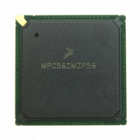
MPC562MZP56 Freescale Semiconductor, MPC562MZP56 Datasheet - Page 43

MPC562MZP56
Manufacturer Part Number
MPC562MZP56
Description
IC MPU 32BIT 56MHZ PPC 388-PBGA
Manufacturer
Freescale Semiconductor
Series
MPC5xxr
Datasheet
1.MPC561MZP56.pdf
(1420 pages)
Specifications of MPC562MZP56
Core Processor
PowerPC
Core Size
32-Bit
Speed
56MHz
Connectivity
CAN, EBI/EMI, SCI, SPI, UART/USART
Peripherals
POR, PWM, WDT
Number Of I /o
64
Program Memory Type
ROMless
Ram Size
32K x 8
Voltage - Supply (vcc/vdd)
2.5 V ~ 2.7 V
Data Converters
A/D 32x10b
Oscillator Type
External
Operating Temperature
-40°C ~ 125°C
Package / Case
388-BGA
Processor Series
MPC5xx
Core
PowerPC
Data Bus Width
32 bit
Data Ram Size
8 KB
Interface Type
SCI, SPI, UART
Maximum Clock Frequency
40 MHz
Number Of Programmable I/os
56
Number Of Timers
22
Operating Supply Voltage
2.6 V to 5 V
Maximum Operating Temperature
+ 85 C
Mounting Style
SMD/SMT
Minimum Operating Temperature
- 40 C
On-chip Adc
2 (10 bit, 32 Channel)
For Use With
MPC564EVB - KIT EVAL FOR MPC561/562/563/564
Lead Free Status / RoHS Status
Request inventory verification / Request inventory verification
Eeprom Size
-
Program Memory Size
-
Lead Free Status / Rohs Status
No
Available stocks
Company
Part Number
Manufacturer
Quantity
Price
Company:
Part Number:
MPC562MZP56
Manufacturer:
FREESCAL
Quantity:
204
Company:
Part Number:
MPC562MZP56
Manufacturer:
Freescale Semiconductor
Quantity:
10 000
Part Number:
MPC562MZP56
Manufacturer:
FREESCALE
Quantity:
20 000
Company:
Part Number:
MPC562MZP56R2
Manufacturer:
RFT
Quantity:
1 441
Company:
Part Number:
MPC562MZP56R2
Manufacturer:
Freescale Semiconductor
Quantity:
10 000
- Current page: 43 of 1420
- Download datasheet (11Mb)
6-39
6-40
6-41
6-42
6-43
7-1
7-2
7-3
7-4
7-5
7-6
7-7
8-1
8-2
8-3
8-4
8-5
8-6
8-7
8-8
8-9
8-10
8-11
8-12
8-13
8-14
8-15
8-16
8-17
8-18
8-19
9-1
9-2
9-3
9-4
9-5
9-6
9-7
9-8
Freescale Semiconductor
Figure
Number
Periodic Interrupt Timer Count (PITC) .................................................................................. 6-45
Periodic Interrupt Timer Register (PITR)............................................................................... 6-45
SGPIO Data Register 1 (SGPIODT1) .................................................................................... 6-46
SGPIO Data Register 2 (SGPIODT2) .................................................................................... 6-47
SGPIO Control Register (SGPIOCR)..................................................................................... 6-48
Reset Status Register (RSR) ..................................................................................................... 7-5
Reset Configuration Basic Scheme........................................................................................... 7-8
Reset Configuration Sampling Scheme for
“Short” PORESET Assertion, Limp Mode Disabled ............................................................... 7-9
Reset Configuration Timing for “Short” PORESET Assertion, Limp Mode Enabled............. 7-9
Reset Configuration Timing for “Long” PORESET Assertion, Limp Mode Disabled.......... 7-10
Reset Configuration Sampling Timing Requirements............................................................ 7-10
Reset Configuration Word (RCW) ......................................................................................... 7-11
Clock Unit Block Diagram ....................................................................................................... 8-2
Main System Oscillator Crystal Configuration ........................................................................ 8-3
System PLL Block Diagram ..................................................................................................... 8-5
MPC561/MPC563 Clocks ........................................................................................................ 8-8
General System Clocks Select ................................................................................................ 8-11
Divided System Clocks Timing Diagram ............................................................................... 8-12
Clocks Timing For DFNH = 1 (or DFNL = 0) ....................................................................... 8-13
Clock Source Switching Flow Chart ...................................................................................... 8-15
Low-Power Modes Flow Diagram ......................................................................................... 8-20
IRAMSTBY Regulator Circuit ............................................................................................... 8-23
Basic Power Supply Configuration......................................................................................... 8-24
External Power Supply Scheme.............................................................................................. 8-25
Keep-Alive Register Key State Diagram................................................................................ 8-27
No Standby, No KAPWR, All System Power-On/Off ........................................................... 8-28
Standby and KAPWR, Other Power-On/Off .......................................................................... 8-29
System Clock and Reset Control Register (SCCR) ................................................................ 8-30
PLL, Low-Power, and Reset-Control Register (PLPRCR) .................................................... 8-34
Change of Lock Interrupt Register (COLIR).......................................................................... 8-36
IRAMSTBY Control Register (VSRMCR) ............................................................................ 8-37
Input Sample Window .............................................................................................................. 9-2
MPC561/MPC563 Bus Signals ................................................................................................ 9-3
Basic Transfer Protocol ............................................................................................................ 9-8
Basic Flow Diagram of a Single Beat Read Cycle ................................................................... 9-9
Single Beat Read Cycle – Basic Timing – Zero Wait States.................................................. 9-10
Single Beat Read Cycle – Basic Timing – One Wait State .................................................... 9-11
Basic Flow Diagram of a Single Beat Write Cycle ................................................................ 9-12
Single Beat Basic Write Cycle Timing – Zero Wait States .................................................... 9-13
MPC561/MPC563 Reference Manual, Rev. 1.2
Figures
Title
Number
Page
xliii
Related parts for MPC562MZP56
Image
Part Number
Description
Manufacturer
Datasheet
Request
R
Part Number:
Description:
Mpc562 32 Bit Powerpc Microcontroller
Manufacturer:
Freescale Semiconductor, Inc
Datasheet:

Part Number:
Description:
MPC5 1K0 5%
Manufacturer:
TE Connectivity
Datasheet:

Part Number:
Description:
MPC5 500R 5%
Manufacturer:
TE Connectivity
Datasheet:

Part Number:
Description:
MPC5 5K0 5%
Manufacturer:
Tyco Electronics
Datasheet:

Part Number:
Description:
MPC5 5R0 5%
Manufacturer:
Tyco Electronics
Datasheet:

Part Number:
Description:
MPC5 50K 5%
Manufacturer:
Tyco Electronics
Datasheet:
Part Number:
Description:
Manufacturer:
Freescale Semiconductor, Inc
Datasheet:
Part Number:
Description:
Manufacturer:
Freescale Semiconductor, Inc
Datasheet:
Part Number:
Description:
Manufacturer:
Freescale Semiconductor, Inc
Datasheet:
Part Number:
Description:
Manufacturer:
Freescale Semiconductor, Inc
Datasheet:
Part Number:
Description:
Manufacturer:
Freescale Semiconductor, Inc
Datasheet:


