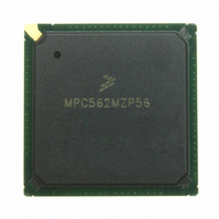
MPC562MZP56 Freescale Semiconductor, MPC562MZP56 Datasheet - Page 53

MPC562MZP56
Manufacturer Part Number
MPC562MZP56
Description
IC MPU 32BIT 56MHZ PPC 388-PBGA
Manufacturer
Freescale Semiconductor
Series
MPC5xxr
Datasheet
1.MPC561MZP56.pdf
(1420 pages)
Specifications of MPC562MZP56
Core Processor
PowerPC
Core Size
32-Bit
Speed
56MHz
Connectivity
CAN, EBI/EMI, SCI, SPI, UART/USART
Peripherals
POR, PWM, WDT
Number Of I /o
64
Program Memory Type
ROMless
Ram Size
32K x 8
Voltage - Supply (vcc/vdd)
2.5 V ~ 2.7 V
Data Converters
A/D 32x10b
Oscillator Type
External
Operating Temperature
-40°C ~ 125°C
Package / Case
388-BGA
Processor Series
MPC5xx
Core
PowerPC
Data Bus Width
32 bit
Data Ram Size
8 KB
Interface Type
SCI, SPI, UART
Maximum Clock Frequency
40 MHz
Number Of Programmable I/os
56
Number Of Timers
22
Operating Supply Voltage
2.6 V to 5 V
Maximum Operating Temperature
+ 85 C
Mounting Style
SMD/SMT
Minimum Operating Temperature
- 40 C
On-chip Adc
2 (10 bit, 32 Channel)
For Use With
MPC564EVB - KIT EVAL FOR MPC561/562/563/564
Lead Free Status / RoHS Status
Request inventory verification / Request inventory verification
Eeprom Size
-
Program Memory Size
-
Lead Free Status / Rohs Status
No
Available stocks
Company
Part Number
Manufacturer
Quantity
Price
Company:
Part Number:
MPC562MZP56
Manufacturer:
FREESCAL
Quantity:
204
Company:
Part Number:
MPC562MZP56
Manufacturer:
Freescale Semiconductor
Quantity:
10 000
Part Number:
MPC562MZP56
Manufacturer:
FREESCALE
Quantity:
20 000
Company:
Part Number:
MPC562MZP56R2
Manufacturer:
RFT
Quantity:
1 441
Company:
Part Number:
MPC562MZP56R2
Manufacturer:
Freescale Semiconductor
Quantity:
10 000
- Current page: 53 of 1420
- Download datasheet (11Mb)
21-9
21-10
21-11
22-1
22-2
22-3
22-4
22-5
22-6
22-7
22-8
22-9
22-10
22-11
22-12
23-1
23-2
23-3
23-4
23-5
23-6
23-7
23-8
23-9
23-10
23-11
23-12
23-13
23-14
23-15
23-16
23-17
23-18
23-19
23-20
23-21
23-22
23-23
23-24
23-25
Freescale Semiconductor
Figure
Number
Program State Diagram......................................................................................................... 21-23
Erase State Diagram.............................................................................................................. 21-27
Censorship States and Transitions ........................................................................................ 21-33
System Block Diagram ........................................................................................................... 22-2
MPC561/MPC563 Memory Map with CALRAM Address Ranges ...................................... 22-3
Standby Power Supply Configuration for CALRAM Array .................................................. 22-4
CALRAM Array ..................................................................................................................... 22-7
CALRAM Module Overlay Map of Flash (CLPS = 0) .......................................................... 22-8
CALRAM Address Map (CLPS = 0) ..................................................................................... 22-9
CALRAM Module Overlay Map of Flash (CLPS = 1) ........................................................ 22-10
CALRAM Address Map (CLPS = 1) ................................................................................... 22-11
CALRAM Module Configuration Register (CRAMMCR).................................................. 22-13
CALRAM Region Base Address Register (CRAM_RBAx) ................................................ 22-16
CALRAM Overlay Configuration Register (CRAM_OVLCR)........................................... 22-17
CALRAM Ownership Trace Register (CRAM_OTR) ......................................................... 22-18
Watchpoint and Breakpoint Support in the CPU.................................................................... 23-9
Partially Supported Watchpoint/Breakpoint Example.......................................................... 23-13
Instruction Support General Structure .................................................................................. 23-15
Load/Store Support General Structure.................................................................................. 23-18
Functional Diagram of MPC561/MPC563 Debug Mode Support ....................................... 23-21
Debug Mode Logic ............................................................................................................... 23-23
BDM Mode Selection ........................................................................................................... 23-24
Debug Mode Reset Configuration ........................................................................................ 23-25
Asynchronous Clock Serial Communications ...................................................................... 23-32
Synchronous Self Clock Serial Communication .................................................................. 23-32
Enabling Clock Mode Following Reset................................................................................ 23-33
Download Procedure Code Example .................................................................................... 23-37
Slow Download Procedure Loop .......................................................................................... 23-38
Fast Download Procedure Loop ........................................................................................... 23-38
Comparator A–D Value Register (CMPA–CMPD).............................................................. 23-41
Exception Cause Register (ECR).......................................................................................... 23-42
Debug Enable Register (DER).............................................................................................. 23-43
Breakpoint Counter B Value and Control Register (COUNTB) .......................................... 23-46
Comparator E–F Value Registers (CMPE–CMPF) .............................................................. 23-46
Comparator G–H Value Registers (CMPG–CMPH)............................................................ 23-47
L-Bus Support Control Register 1 (LCTRL) ........................................................................ 23-47
L-Bus Support Control Register 2 (LCTRL2) ...................................................................... 23-48
I-Bus Support Control Register (ICTRL) ............................................................................. 23-51
Breakpoint Address Register (BAR) .................................................................................... 23-53
Breakpoint Counter A Value and Control Register (COUNTA)......................................... 23-45
MPC561/MPC563 Reference Manual, Rev. 1.2
Figures
Title
Number
Page
liii
Related parts for MPC562MZP56
Image
Part Number
Description
Manufacturer
Datasheet
Request
R
Part Number:
Description:
Mpc562 32 Bit Powerpc Microcontroller
Manufacturer:
Freescale Semiconductor, Inc
Datasheet:

Part Number:
Description:
MPC5 1K0 5%
Manufacturer:
TE Connectivity
Datasheet:

Part Number:
Description:
MPC5 500R 5%
Manufacturer:
TE Connectivity
Datasheet:

Part Number:
Description:
MPC5 5K0 5%
Manufacturer:
Tyco Electronics
Datasheet:

Part Number:
Description:
MPC5 5R0 5%
Manufacturer:
Tyco Electronics
Datasheet:

Part Number:
Description:
MPC5 50K 5%
Manufacturer:
Tyco Electronics
Datasheet:
Part Number:
Description:
Manufacturer:
Freescale Semiconductor, Inc
Datasheet:
Part Number:
Description:
Manufacturer:
Freescale Semiconductor, Inc
Datasheet:
Part Number:
Description:
Manufacturer:
Freescale Semiconductor, Inc
Datasheet:
Part Number:
Description:
Manufacturer:
Freescale Semiconductor, Inc
Datasheet:
Part Number:
Description:
Manufacturer:
Freescale Semiconductor, Inc
Datasheet:


