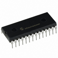
PIC16F57-I/P Microchip Technology, PIC16F57-I/P Datasheet - Page 38

PIC16F57-I/P
Manufacturer Part Number
PIC16F57-I/P
Description
IC MCU FLASH 2KX12 28DIP
Manufacturer
Microchip Technology
Series
PIC® 16Fr
Datasheets
1.PIC16F54-ISS.pdf
(88 pages)
2.PIC16F57-ISS.pdf
(16 pages)
3.PIC16F57-ISO.pdf
(86 pages)
Specifications of PIC16F57-I/P
Program Memory Type
FLASH
Program Memory Size
3KB (2K x 12)
Package / Case
28-DIP (0.600", 15.24mm)
Core Processor
PIC
Core Size
8-Bit
Speed
20MHz
Peripherals
POR, WDT
Number Of I /o
20
Ram Size
72 x 8
Voltage - Supply (vcc/vdd)
2 V ~ 5.5 V
Oscillator Type
External
Operating Temperature
-40°C ~ 85°C
Processor Series
PIC16F
Core
PIC
Data Bus Width
8 bit
Data Ram Size
72 B
Maximum Clock Frequency
20 MHz
Number Of Programmable I/os
20
Number Of Timers
1
Operating Supply Voltage
2 V to 5.5 V
Maximum Operating Temperature
+ 85 C
Mounting Style
Through Hole
3rd Party Development Tools
52715-96, 52716-328, 52717-734
Development Tools By Supplier
DV164120, DV164101, ICE2000
Minimum Operating Temperature
- 40 C
Data Rom Size
2 K
Height
3.3 mm
Length
34.67 mm
Supply Voltage (max)
5.5 V
Supply Voltage (min)
2 V
Width
7.24 mm
Lead Free Status / RoHS Status
Lead free / RoHS Compliant
For Use With
XLT28XP - SOCKET TRANSITION ICE 28DIPAC164001 - MODULE SKT PROMATEII 18/28DIP
Eeprom Size
-
Data Converters
-
Connectivity
-
Lead Free Status / Rohs Status
Lead free / RoHS Compliant
Available stocks
Company
Part Number
Manufacturer
Quantity
Price
Company:
Part Number:
PIC16F57-I/P
Manufacturer:
Microchip Technology
Quantity:
26 657
Part Number:
PIC16F57-I/P
Manufacturer:
MICROCHIP/微芯
Quantity:
20 000
PIC16F5X
7.2.1
The prescaler assignment is fully under software control
(i.e., it can be changed “on-the-fly” during program
execution). To avoid an unintended device Reset, the
following instruction sequence (Example 7-1) must be
executed when changing the prescaler assignment
from Timer0 to the WDT.
EXAMPLE 7-1:
FIGURE 7-5:
DS41213D-page 36
CLRWDT
CLRF
MOVLW
OPTION
CLRWDT
MOVLW
OPTION
Note 1:
TMR0
B'00xx1111’ ;Last 3 instructions
B'00xx1xxx’ ;Set Prescaler to
WDT Enable bit
T0CKI
SWITCHING PRESCALER
ASSIGNMENT
Watchdog
pin
Timer
T
CY
( = F
T0CS, T0SE, PSA PS<2:0> are bits in the Option register.
OSC
CHANGING PRESCALER
(TIMER0→WDT)
BLOCK DIAGRAM OF THE TIMER0/WDT PRESCALER
T0SE
;Clear WDT
;Clear TMR0 &
;in this example
;are required only if
;desired
;PS<2:0> are 000 or 001
;desired WDT rate
/4)
(1)
0
1
PSA
M
U
X
(1)
;Prescaler
0
1
T0CS
M
U
X
(1)
0
8-bit Prescaler
8-to-1 MUX
Time-Out
8
MUX
WDT
1
0
1
To change prescaler from the WDT to the Timer0
module, use the sequence shown in Example 7-2. This
sequence must be used even if the WDT is disabled. A
CLRWDT instruction should be executed before
switching the prescaler.
EXAMPLE 7-2:
PSA
CLRWDT
MOVLW
OPTION
M
U
X
(1)
PSA
(1)
B'xxxx0xxx' ;Select TMR0, new
PS<2:0>
Cycles
Sync
2
(1)
CHANGING PRESCALER
(WDT→TIMER0)
© 2007 Microchip Technology Inc.
;Clear WDT and
;prescaler
;prescale value and
;clock source
TMR0 reg
Data Bus
8


