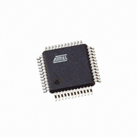
ATSAM3S4AA-AU Atmel, ATSAM3S4AA-AU Datasheet - Page 771

ATSAM3S4AA-AU
Manufacturer Part Number
ATSAM3S4AA-AU
Description
IC MCU 32BIT 256KB FLASH 48LQFP
Manufacturer
Atmel
Series
SAM3Sr
Specifications of ATSAM3S4AA-AU
Core Processor
ARM® Cortex-M3™
Core Size
32-Bit
Speed
64MHz
Connectivity
I²C, MMC, SPI, SSC, UART/USART, USB
Peripherals
Brown-out Detect/Reset, DMA, I²S, POR, PWM, WDT
Number Of I /o
34
Program Memory Size
256KB (256K x 8)
Program Memory Type
FLASH
Ram Size
48K x 8
Voltage - Supply (vcc/vdd)
1.62 V ~ 1.95 V
Data Converters
A/D 8x10/12b
Oscillator Type
Internal
Operating Temperature
-40°C ~ 85°C
Package / Case
48-LQFP
Controller Family/series
ATSAM3S
No. Of I/o's
34
Ram Memory Size
48KB
Cpu Speed
64MHz
No. Of Timers
6
Rohs Compliant
Yes
Package
48LQFP
Device Core
ARM Cortex M3
Family Name
AT91
Maximum Speed
64 MHz
Operating Supply Voltage
1.8|3.3 V
Data Bus Width
32 Bit
Number Of Programmable I/os
34
Interface Type
I2C/I2S/SPI/UART/USART/USB
On-chip Adc
9-chx12-bit
Number Of Timers
3
Lead Free Status / RoHS Status
Lead free / RoHS Compliant
Eeprom Size
-
Available stocks
Company
Part Number
Manufacturer
Quantity
Price
Company:
Part Number:
ATSAM3S4AA-AU
Manufacturer:
ON
Quantity:
2 001
- Current page: 771 of 1118
- Download datasheet (24Mb)
SAM3S Preliminary
One of the POSEN or SPEEDEN bits must be also enabled.
• POSEN: POSition ENabled
0 = disable position.
1 = enables the position measure on channel 0 and 1
• SPEEDEN: SPEED ENabled
0 = disabled.
1 = enables the speed measure on channel 0, the time base being provided by channel 2.
• QDTRANS: Quadrature Decoding TRANSparent
0 = full quadrature decoding logic is active (direction change detected).
1 = quadrature decoding logic is inactive (direction change inactive) but input filtering and edge detection are performed.
• EDGPHA: EDGe on PHA count mode
0 = edges are detected on both PHA and PHB.
1 = edges are detected on PHA only.
• INVA: INVerted phA
0 = PHA (TIOA0) is directly driving quadrature decoder logic.
1 = PHA is inverted before driving quadrature decoder logic.
• INVB: INVerted phB
0 = PHB (TIOB0) is directly driving quadrature decoder logic.
1 = PHB is inverted before driving quadrature decoder logic.
• SWAP: SWAP PHA and PHB
0 = no swap between PHA and PHB.
1 = swap PHA and PHB internally, prior to driving quadrature decoder logic.
• INVIDX: INVerted InDeX
0 = IDX (TIOA1) is directly driving quadrature logic.
1 = IDX is inverted before driving quadrature logic.
• IDXPHB: InDeX pin is PHB pin
0 = IDX pin of the rotary sensor must drive TIOA1.
1 = IDX pin of the rotary sensor must drive TIOB0.
• FILTER:
0 = IDX,PHA, PHB input pins are not filtered.
1 = IDX,PHA, PHB input pins are filtered using MAXFILT value.
• MAXFILT: MAXimum FILTer
1.. 63: defines the filtering capabilities
Pulses with a period shorter than MAXFILT+1 MCK clock cycles are discarded.
771
6500C–ATARM–8-Feb-11
Related parts for ATSAM3S4AA-AU
Image
Part Number
Description
Manufacturer
Datasheet
Request
R

Part Number:
Description:
KIT EVAL FOR ATSAM3S4C
Manufacturer:
Atmel
Datasheet:

Part Number:
Description:
Development Boards & Kits - ARM EVAL KIT SAM3S8 & SAM3SD8 series
Manufacturer:
Atmel
Datasheet:

Part Number:
Description:
AT91 ARM Cortex M3-based Processor
Manufacturer:
ATMEL [ATMEL Corporation]
Datasheet:

Part Number:
Description:
DEV KIT FOR AVR/AVR32
Manufacturer:
Atmel
Datasheet:

Part Number:
Description:
INTERVAL AND WIPE/WASH WIPER CONTROL IC WITH DELAY
Manufacturer:
ATMEL Corporation
Datasheet:

Part Number:
Description:
Low-Voltage Voice-Switched IC for Hands-Free Operation
Manufacturer:
ATMEL Corporation
Datasheet:

Part Number:
Description:
MONOLITHIC INTEGRATED FEATUREPHONE CIRCUIT
Manufacturer:
ATMEL Corporation
Datasheet:

Part Number:
Description:
AM-FM Receiver IC U4255BM-M
Manufacturer:
ATMEL Corporation
Datasheet:

Part Number:
Description:
Monolithic Integrated Feature Phone Circuit
Manufacturer:
ATMEL Corporation
Datasheet:

Part Number:
Description:
Multistandard Video-IF and Quasi Parallel Sound Processing
Manufacturer:
ATMEL Corporation
Datasheet:

Part Number:
Description:
High-performance EE PLD
Manufacturer:
ATMEL Corporation
Datasheet:

Part Number:
Description:
8-bit Flash Microcontroller
Manufacturer:
ATMEL Corporation
Datasheet:


