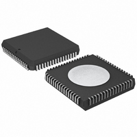
P80C592FFA/00,512 NXP Semiconductors, P80C592FFA/00,512 Datasheet - Page 24

P80C592FFA/00,512
Manufacturer Part Number
P80C592FFA/00,512
Description
IC 80C51 MCU 8BIT ROMLESS 68PLCC
Manufacturer
NXP Semiconductors
Series
80Cr
Datasheet
1.P80C592FFA00512.pdf
(108 pages)
Specifications of P80C592FFA/00,512
Program Memory Type
ROMless
Package / Case
68-PLCC
Core Processor
8051
Core Size
8-Bit
Speed
16MHz
Connectivity
CAN, EBI/EMI, UART/USART
Peripherals
DMA, POR, PWM, WDT
Number Of I /o
48
Ram Size
512 x 8
Voltage - Supply (vcc/vdd)
4.5 V ~ 5.5 V
Data Converters
A/D 8x10b
Oscillator Type
Internal
Operating Temperature
-40°C ~ 85°C
Processor Series
P80C5x
Core
80C51
Data Bus Width
8 bit
Data Ram Size
512 B
Interface Type
CAN/UART
Maximum Clock Frequency
16 MHz
Number Of Programmable I/os
40
Number Of Timers
3
Maximum Operating Temperature
+ 85 C
Mounting Style
SMD/SMT
3rd Party Development Tools
PK51, CA51, A51, ULINK2
Minimum Operating Temperature
- 40 C
On-chip Adc
8-ch x 10-bit
Cpu Family
80C
Device Core
80C51
Device Core Size
8b
Frequency (max)
16MHz
Program Memory Size
Not Required
Total Internal Ram Size
512Byte
# I/os (max)
40
Number Of Timers - General Purpose
3
Operating Supply Voltage (typ)
5V
Operating Supply Voltage (max)
5.5V
Operating Supply Voltage (min)
4.5V
Instruction Set Architecture
CISC
Operating Temp Range
-40C to 85C
Operating Temperature Classification
Industrial
Mounting
Surface Mount
Pin Count
68
Package Type
PLCC
Lead Free Status / RoHS Status
Lead free / RoHS Compliant
Eeprom Size
-
Program Memory Size
-
Lead Free Status / Rohs Status
Compliant
Other names
568-1241-5
935086530512
P80C592FFAA
935086530512
P80C592FFAA
Available stocks
Company
Part Number
Manufacturer
Quantity
Price
Company:
Part Number:
P80C592FFA/00,512
Manufacturer:
ON
Quantity:
300
Company:
Part Number:
P80C592FFA/00,512
Manufacturer:
NXP Semiconductors
Quantity:
10 000
Philips Semiconductors
11.2.3
Table 22 Timer Interrupt Flag register (address C8H)
Table 23 Description of the TM2IR bits (see notes 1 and 2)
Notes
1. Interrupt Enable IEN1 is used to enable/disable Timer 2 interrupts (see Section 14.1.2).
2. Interrupt Priority Register IP1 is used to determine the Timer 2 interrupt priority (see Section 14.1.4).
11.2.4
Table 24 Set Enable register (address EEH)
Table 25 Description of the STE bits (see notes 1 and 2)
Notes
1. If STE.n is LOW then P4.n is not affected by a match of CM0 and T2 (n = 0, 1, 2, 3, 4, 5).
2. STE.6 and STE.7 are read only.
1996 Jun 27
8-bit microcontroller with on-chip CAN
T2OV
TG47
BIT
BIT
7
7
6
5
4
3
2
1
0
7
7
6
5
4
3
2
1
0
T
S
IMER
ET
E
NABLE REGISTER
I
T2OV
CMI2
CMI1
CMI0
CTI3
CTI2
CTI1
CTI0
TG47
TG46
SP45
SP44
SP43
SP42
SP41
SP40
NTERRUPT
SYMBOL
SYMBOL
TG46
CMI2
6
6
F
LAG REGISTER
T2: 16-bit overflow interrupt flag
CM2: interrupt flag
CM1: interrupt flag
CM0: interrupt flag
CT3: interrupt flag
CT2: interrupt flag
CT1: interrupt flag
CT0: interrupt flag
if HIGH then P4.7 is reset on the next toggle, if LOW P4.7 is set on the next toggle
if HIGH then P4.6 is reset on the next toggle, if LOW P4.6 is set on the next toggle
if HIGH then P4.5 is set on a match of CM0 and T2
if HIGH then P4.4 is set on a match of CM0 and T2
if HIGH then P4.3 is set on a match of CM0 and T2
if HIGH then P4.2 is set on a match of CM0 and T2
if HIGH then P4.1 is set on a match of CM0 and T2
if HIGH then P4.0 is set on a match of CM0 and T2
(STE)
SP45
CMI1
5
5
(TM2IR)
CMI0
SP44
4
4
24
SP43
CTI3
3
3
FUNCTION
FUNCTION
SP42
CTI2
2
2
SP41
CTI1
1
1
Product specification
P8xC592
SP40
CTI0
0
0


