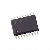
Z86E0208SSG1925 Zilog, Z86E0208SSG1925 Datasheet - Page 33

Z86E0208SSG1925
Manufacturer Part Number
Z86E0208SSG1925
Description
IC Z8 512 BYTE OTP 8MHZ 18-SOIC
Manufacturer
Zilog
Series
Z8®r
Datasheet
1.Z86E0208PSG1925.pdf
(60 pages)
Specifications of Z86E0208SSG1925
Core Processor
Z8
Core Size
8-Bit
Speed
8MHz
Peripherals
POR, WDT
Number Of I /o
14
Program Memory Size
512B (512 x 8)
Program Memory Type
OTP
Ram Size
61 x 8
Voltage - Supply (vcc/vdd)
3.5 V ~ 5.5 V
Oscillator Type
Internal
Operating Temperature
0°C ~ 70°C
Package / Case
18-SOIC (7.5mm Width)
Processor Series
Z86E02x
Core
Z8
Data Bus Width
8 bit
Data Ram Size
61 B
Maximum Clock Frequency
8 MHz
Number Of Programmable I/os
14
Number Of Timers
1
Operating Supply Voltage
4.5 V to 5.5 V
Maximum Operating Temperature
+ 70 C
Mounting Style
SMD/SMT
Minimum Operating Temperature
0 C
Lead Free Status / RoHS Status
Lead free / RoHS Compliant
Eeprom Size
-
Data Converters
-
Connectivity
-
Lead Free Status / Rohs Status
Details
PS014802-0903
Hardware Work Around on the on the Z86CCP01ZEM Emulator
to P32 Rising Edge Digital Interrupt
Hardware Work Around on the on the Z86CCP01ZEM Emulator
to P32 Rising Edge Analog Interrupt
ation, Port 3 data inputs, or T
disabled, freeing the reference input (P33) for use as IRQ1 and/or P33 input.
The comparator requires two NOPs to be stable after setting the enable bit.
ZiLOG recommends that interrupts IRQ0, IRQ1, and IRQ2 be disabled before set-
ting the enable bit. After enabling the comparator, IRQ0, IRQ1, and IRQ2 should
be cleared prior to re-enabling the interrupts. ZiLOG also recommends clearing
these interrupts when disabling the comparator.
To emulate the P32 rising edge digital interrupt the emulator must be modified in
the following way:
1. Connect P32 by soldering a wire jumper from either emulation socket (P3, pin
2. Connect 74HCT04 U27 pin 2 by soldering a wire jumper from U27 pin 2 to P30
To emulate the P32 rising edge analog interrupt the emulator must be modified in
the following way:
1. Connect P32 by soldering a wire jumper from either emulation socket (P2, pin
2. Connect 74HCT04 U27 pin 2 by soldering a wire jumper from U27 pin 2 to P30
The following routine must be added to the initialization of the device:
17) or (P2, pin 12) to 74HCT04 U27 pin 1.
on either emulator socket (P3, pin 25) or (P2, pin 18).
16) or (P1, pin 23) to 74HCT04 U27 pin 1.
on either emulator socket (P3, pin 25) or (P2, pin 18).
HSWP32AFIX
IN
through P31. Alternatively, the comparators can be
Push RP
LD RP, #0Fh
LD R0, #0FFh
POP RP
General-Purpose OTP MCU with 14 I/O Lines
Z86E02 SL 1925
27


