PIC17C42-25/JW Microchip Technology, PIC17C42-25/JW Datasheet - Page 37
PIC17C42-25/JW
Manufacturer Part Number
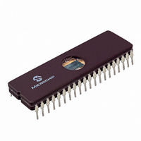
PIC17C42-25/JW
Description
MICRO CTRL 2K X 16 EPROM 40 CDIP
Manufacturer
Microchip Technology
Series
PIC® 17Cr
Specifications of PIC17C42-25/JW
Core Processor
PIC
Core Size
8-Bit
Speed
25MHz
Connectivity
UART/USART
Peripherals
POR, PWM, WDT
Number Of I /o
33
Program Memory Size
4KB (2K x 16)
Program Memory Type
EPROM, UV
Ram Size
232 x 8
Voltage - Supply (vcc/vdd)
4.5 V ~ 5.5 V
Oscillator Type
External
Operating Temperature
0°C ~ 70°C
Package / Case
40-CDIP (0.600", 15.24mm) Window
For Use With
AC174001 - MODULE SKT PROMATEII 40DIP
Lead Free Status / RoHS Status
Contains lead / RoHS non-compliant
Eeprom Size
-
Data Converters
-
Other names
PIC17C42/JW


6.2.2.2
The CPUSTA register contains the status and control
bits for the CPU. This register is used to globally
enable/disable interrupts. If only a specific interrupt is
desired to be enabled/disabled, please refer to the
INTerrupt STAtus (INTSTA) register and the Peripheral
Interrupt Enable (PIE) register. This register also indi-
cates if the stack is available and contains the
Power-down (PD) and Time-out (TO) bits. The TO, PD,
and STKAV bits are not writable. These bits are set and
cleared according to device logic. Therefore, the result
of an instruction with the CPUSTA register as destina-
tion may be different than intended.
FIGURE 6-8:
1996 Microchip Technology Inc.
bit7
bit 7-6: Unimplemented: Read as '0'
bit 5:
bit 4:
bit 3:
bit 2:
bit 1-0: Unimplemented: Read as '0'
U - 0
—
CPU STATUS REGISTER (CPUSTA)
STKAV: Stack Available bit
This bit indicates that the 4-bit stack pointer value is Fh, or has rolled over from Fh
1 = Stack is available
0 = Stack is full, or a stack overflow may have occurred (Once this bit has been cleared by a
GLINTD: Global Interrupt Disable bit
This bit disables all interrupts. When enabling interrupts, only the sources with their enable bits set can
cause an interrupt.
1 = Disable all interrupts
0 = Enables all un-masked interrupts
TO: WDT Time-out Status bit
1 = After power-up or by a CLRWDT instruction
0 = A Watchdog Timer time-out occurred
PD: Power-down Status bit
1 = After power-up or by the CLRWDT instruction
0 = By execution of the SLEEP instruction
U - 0
stack overflow, only a device reset will set this bit)
—
CPUSTA REGISTER (ADDRESS: 06h, UNBANKED)
STKAV GLINTD
R - 1
R/W - 1
R - 1
TO
R - 1
PD
U - 0
—
U - 0
—
bit0
R = Readable bit
W = Writable bit
U = Unimplemented bit,
- n = Value at POR reset
Read as ‘0’
PIC17C4X
0h (stack overflow).
DS30412C-page 37
Related parts for PIC17C42-25/JW
Image
Part Number
Description
Manufacturer
Datasheet
Request
R

Part Number:
Description:
High-Performance 8-Bit CMOS EPROM/ROM Microcontroller
Manufacturer:
Microchip Technology
Datasheet:

Part Number:
Description:
Manufacturer:
Microchip Technology Inc.
Datasheet:
Part Number:
Description:
Manufacturer:
Microchip Technology Inc.
Datasheet:
Part Number:
Description:
Manufacturer:
Microchip Technology Inc.
Datasheet:
Part Number:
Description:
Manufacturer:
Microchip Technology Inc.
Datasheet:
Part Number:
Description:
Manufacturer:
Microchip Technology Inc.
Datasheet:
Part Number:
Description:
Manufacturer:
Microchip Technology Inc.
Datasheet:
Part Number:
Description:
Manufacturer:
Microchip Technology Inc.
Datasheet:
Part Number:
Description:
Manufacturer:
Microchip Technology Inc.
Datasheet: