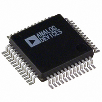
ADUC836BS Analog Devices Inc, ADUC836BS Datasheet - Page 5

ADUC836BS
Manufacturer Part Number
ADUC836BS
Description
IC ADC DUAL 16BIT W/MCU 52-MQFP
Manufacturer
Analog Devices Inc
Series
MicroConverter® ADuC8xxr
Datasheet
1.ADUC836BSZ.pdf
(80 pages)
Specifications of ADUC836BS
Rohs Status
RoHS non-compliant
Core Processor
8052
Core Size
8-Bit
Speed
12.58MHz
Connectivity
EBI/EMI, I²C, SPI, UART/USART
Peripherals
POR, PSM, PWM, Temp Sensor, WDT
Number Of I /o
34
Program Memory Size
62KB (62K x 8)
Program Memory Type
FLASH
Eeprom Size
4K x 8
Ram Size
2.25K x 8
Voltage - Supply (vcc/vdd)
2.7 V ~ 5.25 V
Data Converters
A/D 7x16b; D/A 1x12b
Oscillator Type
Internal
Operating Temperature
-40°C ~ 125°C
Package / Case
52-MQFP, 52-PQFP
Available stocks
Company
Part Number
Manufacturer
Quantity
Price
Company:
Part Number:
ADUC836BS
Manufacturer:
ADI
Quantity:
250
Part Number:
ADUC836BS
Manufacturer:
ADI/亚德诺
Quantity:
20 000
Company:
Part Number:
ADUC836BSZ
Manufacturer:
ADI
Quantity:
150
Company:
Part Number:
ADUC836BSZ
Manufacturer:
Analog Devices Inc
Quantity:
10 000
Part Number:
ADUC836BSZ
Manufacturer:
ADI/亚德诺
Quantity:
20 000
Parameter
TRANSDUCER BURNOUT CURRENT SOURCES
EXCITATION CURRENT SOURCES
LOGIC INPUTS
CRYSTAL OSCILLATOR (XTAL1 AND XTAL2)
REV. A
AIN+ Current
AIN– Current
All Inputs Except SCLOCK, RESET,
Initial Tolerance @ 25°C
Drift
Output Current
Drift
Initial Current Matching @ 25°C
Drift Matching
Line Regulation (AV
Load Regulation
Output Compliance
SCLOCK and RESET Only
Input Currents
Input Capacitance
Logic Inputs, XTAL1 Only
XTAL1 Input Capacitance
XTAL2 Output Capacitance
V
V
V
V
V
V
V
Initial Tolerance @ 25°C
and XTAL1
(Schmitt-Triggered Inputs)
Port 0, P1.2–P1.7, EA
SCLOCK, MOSI, MISO, SS
RESET
P1.0, P1.1, Ports 2 and 3
INL
INH
T+
T–
T+ –
INL
INH
, Input Low Voltage
, Input Low Voltage
, Input High Voltage
, Input High Voltage
V
T–
2
2
DD
)
2
2
13
ADuC836
–100
+100
±10
0.03
–200
±10
200
±1
20
1
0.1
AV
AGND
0.8
0.4
2.0
1.3/3
0.95/2.5
0.8/1.4
0.4/1.1
0.3/0.85
0.3/0.85
±10
–10 min, –40 max
±10
±10
35 min, 105 max
±10
–180
–660
–20
–75
5
0.8
0.4
3.5
2.5
18
18
DD
– 0.6
–5–
Test Conditions/Comments
AIN+ Is the Selected Positive Input
to the Primary ADC
AIN– Is the Selected Negative Input
to the Auxiliary ADC
Available from Each Current Source
Matching between Both Current Sources
AV
DV
DV
DV
DV
DV
DV
DV
DV
V
V
V
V
V
Internal Pull-Down
V
V
V
All Digital Inputs
DV
DV
DV
DV
IN
IN
IN
IN
IN
IN
IN
IN
DD
DD
DD
DD
DD
DD
DD
DD
DD
DD
DD
DD
DD
= 0 V or V
= 0 V, DV
= V
= 0 V, DV
= V
= V
= 2 V, DV
= 450 mV, DV
= 5 V + 5%
= 5 V
= 3 V
= 5 V
= 3 V
= 5 V
= 3 V
= 5 V
= 3 V
= 5 V
= 3 V
= 5 V
= 3 V
DD
DD
DD
, DV
, DV
, DV
DD
DD
DD
DD
DD
DD
DD
= 5 V, Internal Pull-Up
= 5 V
= 5 V
= 5 V
= 5 V,
= 5 V
DD
= 5 V
V max
V min
V min
Unit
nA typ
nA typ
% typ
%/°C typ
A typ
% typ
ppm/°C typ
% typ
ppm/°C typ
A/V typ
A/V typ
V max
V max
V min/V max
V min/V max
V min/V max
V min/V max
V min/V max
V min/V max
A max
A min/A max
A max
A max
A min/A max
A max
A min
A max
A min
A max
pF typ
V max
V max
V min
V min
pF typ
pF typ
ADuC836


