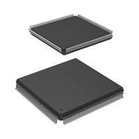
R5S72030W200FP Renesas Electronics America, R5S72030W200FP Datasheet - Page 973

R5S72030W200FP
Manufacturer Part Number
R5S72030W200FP
Description
IC SUPERH MPU ROMLESS 240QFP
Manufacturer
Renesas Electronics America
Series
SuperH® SH7200r
Specifications of R5S72030W200FP
Core Processor
SH2A-FPU
Core Size
32-Bit
Speed
200MHz
Connectivity
CAN, I²C, SCI, SSI, SSU, USB
Peripherals
DMA, LCD, POR, PWM, WDT
Number Of I /o
82
Program Memory Type
ROMless
Ram Size
80K x 8
Voltage - Supply (vcc/vdd)
1.1 V ~ 3.6 V
Data Converters
A/D 8x10b; D/A 2x8b
Oscillator Type
Internal
Operating Temperature
-20°C ~ 85°C
Package / Case
240-QFP
For Use With
R0K572030S000BE - KIT DEV FOR SH7203HS0005KCU11H - EMULATOR E10A-USB H8S(X),SH2(A)
Lead Free Status / RoHS Status
Contains lead / RoHS non-compliant
Eeprom Size
-
Program Memory Size
-
Available stocks
Company
Part Number
Manufacturer
Quantity
Price
Company:
Part Number:
R5S72030W200FP
Manufacturer:
SAMSUNG
Quantity:
1 001
Company:
Part Number:
R5S72030W200FP
Manufacturer:
Renesas Electronics America
Quantity:
10 000
- Current page: 973 of 1686
- Download datasheet (10Mb)
Bit 5 — Sleep Mode (MCR5): Enables or disables Sleep mode transition. If this bit is set, while
RCAN-TL1 is in halt mode, the transition to sleep mode is enabled. Setting MCR5 is allowed after
entering Halt mode. The two Error Counters (REC, TEC) will remain the same during Sleep
mode. This mode will be exited in two ways:
1. by writing a ‘0’ to this bit position,
2. or, if MCR[7] is enabled, after detecting a dominant bit on the CAN bus.
If Auto wake up mode is disabled, RCAN-TL1 will ignore all CAN bus activities until the sleep
mode is terminated. When leaving this mode the RCAN-TL1 will synchronise to the CAN bus (by
checking for 11 recessive bits) before joining CAN Bus activity. This means that, when the No.2
method is used, RCAN-TL1 will miss the first message to receive. CAN transceivers stand-by
mode will also be unable to cope with the first message when exiting stand by mode, and the S/W
needs to be designed in this manner.
In sleep mode only the following registers can be accessed: MCR, GSR, IRR and IMR.
Important: RCAN-TL1 is required to be in Halt mode before requesting to enter in Sleep mode.
That allows the CPU to clear all pending interrupts before entering sleep mode. Once all interrupts
are cleared RCAN-TL1 must leave the Halt mode and enter Sleep mode simultaneously (by
writing MCR[5] = 1 and MCR[1] = 0 at the same time).
Bit 4 — Reserved. The written value should always be ‘0’ and the returned value is ‘0’.
Bit 3 — Reserved. The written value should always be ‘0’ and the returned value is ‘0’.
Bit 2 — Message Transmission Priority (MCR2): MCR2 selects the order of transmission for
pending transmit data. If this bit is set, pending transmit data are sent in order of the bit position in
the Transmission Pending Register (TXPR). The order of transmission starts from Mailbox-31 as
the highest priority, and then down to Mailbox-1 (if those mailboxes are configured for
transmission). Please note that this feature cannot be used for time trigger transmission of the
Mailboxes 24 to 30.
If MCR2 is cleared, all messages for transmission are queued with respect to their priority (by
running internal arbitration). The highest priority message has the Arbitration Field (STDID + IDE
bit + EXTID (if IDE = 1) + RTR bit) with the lowest digital value and is transmitted first. The
internal arbitration includes the RTR bit and the IDE bit (internal arbitration works in the same
Bit 5: MCR5
0
1
Description
RCAN-TL1 sleep mode released (Initial value)
Transition to RCAN-TL1 sleep mode enabled
Section 19 Controller Area Network (RCAN-TL1)
Rev. 3.00 Sep. 28, 2009 Page 941 of 1650
REJ09B0313-0300
Related parts for R5S72030W200FP
Image
Part Number
Description
Manufacturer
Datasheet
Request
R

Part Number:
Description:
KIT STARTER FOR M16C/29
Manufacturer:
Renesas Electronics America
Datasheet:

Part Number:
Description:
KIT STARTER FOR R8C/2D
Manufacturer:
Renesas Electronics America
Datasheet:

Part Number:
Description:
R0K33062P STARTER KIT
Manufacturer:
Renesas Electronics America
Datasheet:

Part Number:
Description:
KIT STARTER FOR R8C/23 E8A
Manufacturer:
Renesas Electronics America
Datasheet:

Part Number:
Description:
KIT STARTER FOR R8C/25
Manufacturer:
Renesas Electronics America
Datasheet:

Part Number:
Description:
KIT STARTER H8S2456 SHARPE DSPLY
Manufacturer:
Renesas Electronics America
Datasheet:

Part Number:
Description:
KIT STARTER FOR R8C38C
Manufacturer:
Renesas Electronics America
Datasheet:

Part Number:
Description:
KIT STARTER FOR R8C35C
Manufacturer:
Renesas Electronics America
Datasheet:

Part Number:
Description:
KIT STARTER FOR R8CL3AC+LCD APPS
Manufacturer:
Renesas Electronics America
Datasheet:

Part Number:
Description:
KIT STARTER FOR RX610
Manufacturer:
Renesas Electronics America
Datasheet:

Part Number:
Description:
KIT STARTER FOR R32C/118
Manufacturer:
Renesas Electronics America
Datasheet:

Part Number:
Description:
KIT DEV RSK-R8C/26-29
Manufacturer:
Renesas Electronics America
Datasheet:

Part Number:
Description:
KIT STARTER FOR SH7124
Manufacturer:
Renesas Electronics America
Datasheet:

Part Number:
Description:
KIT STARTER FOR H8SX/1622
Manufacturer:
Renesas Electronics America
Datasheet:

Part Number:
Description:
KIT DEV FOR SH7203
Manufacturer:
Renesas Electronics America
Datasheet:


