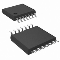
LMV774MTX/NOPB National Semiconductor, LMV774MTX/NOPB Datasheet - Page 15

LMV774MTX/NOPB
Manufacturer Part Number
LMV774MTX/NOPB
Description
IC OPAMP QUAD LO NOISE 14-TSSOP
Manufacturer
National Semiconductor
Datasheet
1.LMV772MMNOPB.pdf
(20 pages)
Specifications of LMV774MTX/NOPB
Amplifier Type
General Purpose
Number Of Circuits
4
Output Type
Rail-to-Rail
Slew Rate
1.4 V/µs
Gain Bandwidth Product
3.5MHz
Current - Input Bias
0.23pA
Voltage - Input Offset
250µV
Current - Supply
600µA
Current - Output / Channel
75mA
Voltage - Supply, Single/dual (±)
2.7 V ~ 5.5 V
Operating Temperature
-40°C ~ 125°C
Mounting Type
Surface Mount
Package / Case
14-TSSOP
Rail/rail I/o Type
Rail to Rail Output
Number Of Elements
4
Unity Gain Bandwidth Product
3.5MHz
Common Mode Rejection Ratio
80dB
Input Offset Voltage
1@5VmV
Input Bias Current
100pA
Single Supply Voltage (typ)
3/5V
Dual Supply Voltage (typ)
Not RequiredV
Voltage Gain In Db
100dB
Power Supply Rejection Ratio
82dB
Power Supply Requirement
Single
Shut Down Feature
No
Single Supply Voltage (min)
2.7V
Single Supply Voltage (max)
5.5V
Dual Supply Voltage (min)
Not RequiredV
Dual Supply Voltage (max)
Not RequiredV
Operating Temp Range
-40C to 125C
Operating Temperature Classification
Automotive
Mounting
Surface Mount
Pin Count
14
Package Type
TSSOP
Lead Free Status / RoHS Status
Lead free / RoHS Compliant
-3db Bandwidth
-
Lead Free Status / Rohs Status
Compliant
Other names
LMV774MTX
Available stocks
Company
Part Number
Manufacturer
Quantity
Price
Company:
Part Number:
LMV774MTX/NOPB
Manufacturer:
TOSHIBA
Quantity:
6 221
HIGH PASS FILTER
In a similar approach, one can derive the transfer function of
a high pass filter. A typical first order high pass filter is shown
below:
Writing the KCL for this circuit :
(V
Solving these two equations to find the transfer function and
using:
(high frequency gain)
Which results:
Looking at the transfer function, it is clear that when f/f
small, the capacitor is open and hence no signal is getting in
to the amplifier. As the frequency increases the amplifier
starts operating. At f = f
circuit and the amplifier will have a constant, high frequency,
gain of H
pass filter:
1
denotes the voltage between C and R
O
.
Figure 6
FIGURE 5. Highpass FIlter
shows the transfer function of this high
O
the capacitor behaves like a short
and
1
)
20039654
(12)
(13)
(14)
O
is
15
BAND PASS FILTER
Combining a low pass filter and a high pass filter will generate
a band pass filter. In this network the input impedance forms
the high pass filter while the feedback impedance forms the
low pass filter. Choosing the corner frequencies so that f
f
through the filter while frequencies below f
be cut off.
The transfer function can be easily calculated using the same
methodology as before.
Where
The transfer function is presented in the following figure.
2
, then all the frequencies in between, f
FIGURE 6. Highpass Filter Transfer Function
FIGURE 7. Bandpass Filter
1
1
≤
and above f
f
≤
20039658
www.national.com
f
20039660
2
, will pass
2
(15)
will
1
<


