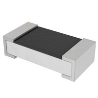
RC0603FR-070RL Yageo, RC0603FR-070RL Datasheet - Page 11

RC0603FR-070RL
Manufacturer Part Number
RC0603FR-070RL
Description
RES 0.0 OHM 1/10W 0603 SMD
Manufacturer
Yageo
Series
RC0603r
Datasheets
1.YC248-JR-07100RL.pdf
(7 pages)
2.YC358TJK-071KL.pdf
(16 pages)
3.RC0603JR-072K7L.pdf
(9 pages)
Specifications of RC0603FR-070RL
Resistance (ohms)
0.0
Power (watts)
0.1W, 1/10W
Composition
Thick Film
Temperature Coefficient
±200ppm/°C
Tolerance
Jumper
Size / Dimension
0.063" L x 0.031" W (1.60mm x 0.80mm)
Height
0.018" (0.45mm)
Lead Style
Surface Mount (SMD - SMT)
Package / Case
0603 (1608 Metric)
Resistance In Ohms
0.0
Case
0603 (1608 metric)
Resistance
0 Ohms
Power Rating
0.1 Watt (1/10 Watt)
Termination Style
SMD/SMT
Voltage Rating
100 Volts
Operating Temperature Range
- 55 C to + 155 C
Dimensions
0.8 mm W x 1.6 mm L x 0.45 mm H
Product
Thick Film Resistors SMD
Features
-
Lead Free Status / Rohs Status
Details
Other names
Q3106287A
Available stocks
Company
Part Number
Manufacturer
Quantity
Price
Company:
Part Number:
RC0603FR-070RL
Manufacturer:
TI
Quantity:
15 600
Part Number:
RC0603FR-070RL
Manufacturer:
YAGEO原装
Quantity:
20 000
Mar 25, 2008 V.7
D
D
S
The resistor is considered to be operating under
single pulse conditions if, during its life, it is loaded
with a limited number (approximately 1,500) of
pulses over long time intervals (greater than one
hour).
R
The resistor is operating under repetitive pulse
conditions if it is loaded by a continuous train of
pulses of similar power.
The dashed line in Fig. 12 shows the observed
maximum load for the Size 1206 chip resistors under
single-pulse loading.
More usually, the resistor must withstand a
continuous train of pulses of repetition time ‘t
during which only a small resistance change is
acceptable. This resistance change (∆R/R) is equal to
the change permissible under continuous load
conditions. The continuous pulse train and small
permissible resistance change reduces the maximum
handling capability.
The continuous pulse train maximum handling
capacity of chip resistors has been determined
experimentally.
Measurements have shown that the handling capacity
varies with the resistive value applied.
However, maximum peak pulse voltages as indicated
in Fig. 13, should not be exceeded.
E
E
INGLE PULSE
EPETITIVE PULSE
F
F
I
I
N
N
I
I
T
T
I
I
O
O
N
N
S
S
O
O
Chip Resistor Surface Mount
F
F
P
P
U
U
L
L
S
S
E
E
S
S
p
’
Thick film technology
D
The graphs in Figs 12 and 13 may be used to
determine the maximum pulse-load for a resistor.
D
E
E
T
T
For repetitive rectangular pulses:
−
−
For repetitive exponential pulses:
−
For single rectangular pulses:
−
−
E
E
R
R
As for rectangular pulses, except that t
by the solid lines of Fig. 12 for the applicable
value of t
in Fig. 13 for the applicable value of t
dashed line of Fig. 12 for the applicable value of
t
in Fig. 13 for the applicable value of t
V ˆ must be lower than the value of
V ˆ must be lower than the value of
V ˆ
V ˆ
i
M
M
R
R
.
i
i
i
i
2
2
I
I
N
N
A
A
must be lower than the value of
must be lower than the
T
INTRODUCTION
T
I
I
O
O
N
N
i
and duty cycle t
O
O
F
F
P
P
U
U
L
L
S
S
E
E
-
-
L
L
O
O
A
A
D
D
p
/t
i
P ˆ
.
max
Product specification
given by the
www.yageo.com
V ˆ
V ˆ
i
i
P ˆ
max
.
max
.
max
i
= 0.5 τ .
given
given
given
11
16


