ATAB5570 Atmel, ATAB5570 Datasheet - Page 9
ATAB5570
Manufacturer Part Number
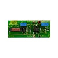
ATAB5570
Description
BOARD EVAL FOR ATAB5570
Manufacturer
Atmel
Type
Development kitr
Specifications of ATAB5570
Contents
Fully Assembled Evaluation Board
Product
RFID Transponders
For Use With/related Products
ATA5570
Lead Free Status / RoHS Status
Contains lead / RoHS non-compliant


5.4
5.5
Figure 5-2.
4863A–RFID–07/05
Block-read Mode
e5550 Sequence Terminator
No terminator
Regular read mode
ST = on
Read Data Stream with Sequence Terminator
With the direct access command, the addressed block is repetitively read only. This mode is
called block-read mode. Direct access is entered by transmitting the page access opcode (“10”
or “11”), a single “0” bit, and the requested 3-bit block address, when the tag is in normal mode.
In password mode (PWD bit set), the direct access to a single block needs the valid 32-bit pass-
word to be transmitted after the page access opcode, whereas a “0” bit and the 3-bit block
address follow afterwards. In case the transmitted password does not match with the contents of
block 7, the ATA5570 tag returns to the regular-read mode.
Note:
The sequence terminator (ST) is a special damping pattern which is inserted before the first
block and may be used to synchronize the reader. This e5550-compatible sequence terminator
consists of four bit periods with underlaying data values of “1”. During the second and the fourth
bit period, modulation is switched off (if Manchester coding is activated, then modulation is
switched on). Bi-phase modulated data blocks need fixed leading and trailing bits in combination
with the sequence terminator to be reliably identified.
The sequence terminator may be individually enabled by setting mode bit 29 (ST = “1”) in the
e5550-compatibility mode (X-mode = “0”).
In the regular-read mode, the sequence terminator is inserted at the start of each MAXBLK-lim-
ited read data stream. In block-read mode, after any block-write or direct access command, or if
MAXBLK was set to “0” or “1”, the sequence terminator is inserted before the transmission of the
selected block.
This behavior is different from former e5550-compatible ICs (T5551, T5554).
Sequence terminator
A direct access to block 0 of page 1 will read the configuration data of block 0, page 0.
A direct access to block 3 to 7 of page 1 reads all data bits as zero.
Block 1
Block 1
Block 2
Block 2
MAXBLK
MAXBLK
Sequence terminator
Block 1
ATA5570 [Preliminary]
Block 1
Block 2
Block 2
9
Related parts for ATAB5570
Image
Part Number
Description
Manufacturer
Datasheet
Request
R

Part Number:
Description:
DEV KIT FOR AVR/AVR32
Manufacturer:
Atmel
Datasheet:

Part Number:
Description:
INTERVAL AND WIPE/WASH WIPER CONTROL IC WITH DELAY
Manufacturer:
ATMEL Corporation
Datasheet:
Part Number:
Description:
Low-Voltage Voice-Switched IC for Hands-Free Operation
Manufacturer:
ATMEL Corporation
Datasheet:
Part Number:
Description:
MONOLITHIC INTEGRATED FEATUREPHONE CIRCUIT
Manufacturer:
ATMEL Corporation
Datasheet:
Part Number:
Description:
AM-FM Receiver IC U4255BM-M
Manufacturer:
ATMEL Corporation
Datasheet:
Part Number:
Description:
Monolithic Integrated Feature Phone Circuit
Manufacturer:
ATMEL Corporation
Datasheet:
Part Number:
Description:
Multistandard Video-IF and Quasi Parallel Sound Processing
Manufacturer:
ATMEL Corporation
Datasheet:
Part Number:
Description:
High-performance EE PLD
Manufacturer:
ATMEL Corporation
Datasheet:
Part Number:
Description:
8-bit Flash Microcontroller
Manufacturer:
ATMEL Corporation
Datasheet:
Part Number:
Description:
2-Wire Serial EEPROM
Manufacturer:
ATMEL Corporation
Datasheet: