AGLP-EVAL-KIT Actel, AGLP-EVAL-KIT Datasheet - Page 29
AGLP-EVAL-KIT
Manufacturer Part Number
AGLP-EVAL-KIT
Description
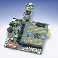
MCU, MPU & DSP Development Tools IGLOO PLUS Starter Kit
Manufacturer
Actel
Datasheet
1.AGLP-EVAL-KIT.pdf
(62 pages)
Specifications of AGLP-EVAL-KIT
Processor To Be Evaluated
CSG289
Interface Type
USB, JTAG
Operating Supply Voltage
1.2 V to 1.5 V
Lead Free Status / RoHS Status
Lead free / RoHS Compliant


Operation of Board Components
Clock Oscillator
Reference
Schematic
Reset
IGLOO PLUS Starter Kit User’s Guide
This chapter describes operation of the IGLOO PLUS evaluation board.
One 20 MHz clock oscillator with 50 PPM is provided on the board. This clock oscillator is connected to the FPGA to
provide a system or reference clock. The PLL can be configured and instantiated in the FPGA to generate a wide range
of clock frequencies.
For more information, refer to the IGLOO PLUS Starter Kit website page:
Figure 4-1
An RC type push-button reset switch to the FPGA is provided on-board. The Schmitt Trigger chip (U13), however, is
NOT populated. An on-board Schmitt Trigger chip is not required because Schmitt Trigger is one of the many
advanced I/O features of the IGLOO PLUS FPGA family. To improve noise immunity, ensure that the Schmitt Trigger
option for this reset input pin is enabled in the FPGA design. If the IGLOO PLUS FPGA is swapped out with a device
that does not have the advance Schmitt Trigger I/O feature, the Schmitt Trigger chip (U13) should be populated.
http://www.actel.com/products/hardware/devkits_boards/iglooplus_starter.aspx.
shows the schematic for the clock oscillator.
V3P3
R43
R43
10K
10K
Figure 4-1 · Clock Oscillator Schematic
Mfg P/N = SIT8002AC-43-33E
Mfg P/N = SIT8002AC-43-33E
Manufacturer = SI TIME
Manufacturer = SI TIME
4
1
VDD
OUT_EN
OSCILLATOR
OSCILLATOR
U10
U10
OUTPUT
GND
3
2
R64
R64
22
22
OSC_CLK
[4]
4
29
Related parts for AGLP-EVAL-KIT
Image
Part Number
Description
Manufacturer
Datasheet
Request
R

Part Number:
Description:
MCU, MPU & DSP Development Tools Silicon Sculptor Programming Mod
Manufacturer:
Actel
Part Number:
Description:
MCU, MPU & DSP Development Tools InSystem Programming ProASICPLUS Devices
Manufacturer:
Actel
Part Number:
Description:
Programming Socket Adapters & Emulators PQ160 Module
Manufacturer:
Actel
Part Number:
Description:
Programming Socket Adapters & Emulators Axcelerator Adap Module Kit
Manufacturer:
Actel
Part Number:
Description:
Programming Socket Adapters & Emulators Evaluation
Manufacturer:
Actel
Part Number:
Description:
Programming Socket Adapters & Emulators AFDX Solutions
Manufacturer:
Actel
Part Number:
Description:
Programming Socket Adapters & Emulators SILICON SCULPTOR ADAPTER MODULE
Manufacturer:
Actel
Datasheet:
Part Number:
Description:
Programming Socket Adapters & Emulators Axcelerator Adap Module Kit
Manufacturer:
Actel
Part Number:
Description:
Programming Socket Adapters & Emulators Evaluation
Manufacturer:
Actel
Part Number:
Description:
Programming Socket Adapters & Emulators Silicon Sculptor Software
Manufacturer:
Actel
Part Number:
Description:
Programming Socket Adapters & Emulators InSystem Programming ProASICPLUS Devices
Manufacturer:
Actel
Part Number:
Description:
Programming Socket Adapters & Emulators Evaluation
Manufacturer:
Actel
Part Number:
Description:
Programming Socket Adapters & Emulators Axcelerator Adap Module Kit
Manufacturer:
Actel
Part Number:
Description:
Programming Socket Adapters & Emulators Axcelerator Adap Module Kit
Manufacturer:
Actel
Part Number:
Description:
Programming Socket Adapters & Emulators Axcelerator Adap Module Kit
Manufacturer:
Actel