AGLP-EVAL-KIT Actel, AGLP-EVAL-KIT Datasheet - Page 43
AGLP-EVAL-KIT
Manufacturer Part Number
AGLP-EVAL-KIT
Description
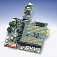
MCU, MPU & DSP Development Tools IGLOO PLUS Starter Kit
Manufacturer
Actel
Datasheet
1.AGLP-EVAL-KIT.pdf
(62 pages)
Specifications of AGLP-EVAL-KIT
Processor To Be Evaluated
CSG289
Interface Type
USB, JTAG
Operating Supply Voltage
1.2 V to 1.5 V
Lead Free Status / RoHS Status
Lead free / RoHS Compliant


USB-to-UART Interface
IGLOO PLUS Starter Kit User’s Guide
6
7
8
9
GND1
GND2
GND3
GND4
Mfr P/N :UX60-MB-5ST
Mfr: Hirose
USB_MINI_RECEP
USB_MINI_RECEP
J5
J5
VBUS
GND
NC
D+
D-
Included on the starter kit board is a USB-to-UART interface with ESD protection. This interface includes an
integrated USB-to-UART bridge controller to provide a standard UART connection with the IGLOO PLUS FPGA.
Any standard UART controller can be implemented in the IGLOO PLUS FPGA to allow access with this interface. In
addition, Actel IP catalog includes various UART controllers, specifically CoreUART, which can be instantiated in the
FPGA design with an embedded processor. CoreUART controller supports both asynchronous and synchronous modes
with configurable parameters for various applications.
One application of the USB-to-UART interface is to allow for Hyper-terminal on a PC to communicate with the
IGLOO PLUS FPGA. HyperTerminal is a serial communications application program that can be installed in the
Windows® operating system. A basic HyperTerminal program is usually distributed with Windows. With an USB
driver properly installed, and correct COM port and communication settings selected, you can use the HyperTerminal
program to communicate with a design running in the IGLOO PLUS FPGA device.
Information on the USB-to-UART bridge datasheet and device drivers are available at the IGLOO PLUS Starter Kit
website page: http://www.actel.com/products/hardware/devkits_boards/iglooplus_starter.aspx.
The USB-to-UART schematic is shown in
1
2
3
4
5
1
2
3
PTC1
PTC1
Mfr P/N :MICROSMD050F-2
Mfr:Tyco
IO1A
G
IO2A
FUSE
FUSE
U1
U1
USBLC6-2
USBLC6-2
Mfr P/N :USBLC6-2SC6
Mfr: ST Micro.
JP1
JP1
CON2
CON2
Figure 4-21 · USB-to-UART Interface Schematic
5V_USB
IO1B
IO2B
V
6
5
4
D9
D9
C18
C18
0.1uF
0.1uF
VUSB
FERRITE BEAD
FERRITE BEAD
R2
R2
147
147
Figure
LED_GREEN
LED_GREEN
FB1
FB1
Mfr P/N :BLM31PG500SN1L
Mfr: Murata
4-21.
1uF
1uF
C2
C2
C1
C1
0.1uF
0.1uF
10
13
14
15
16
17
8
7
6
5
4
VBUS
REGIN
VDD
NC1
NC2
NC3
NC4
NC5
NC6
D-
D+
CP2102
CP2102
U2
U2
NSUSPEND
SUSPEND
Mfr P/N :CP2102-GM
Mfr: Silicon Labs
NC10
NC11
DCD
DTR
RTS
CTS
DSR
RXD
RST
NC7
NC8
NC9
TXD
RI
28
24
23
27
2
1
26
25
12
11
9
18
19
20
21
22
R67
R67
USB-to-UART Interface
0
0
V3P3
R1
R1
10K
10K
AGL_UART_RXD [4]
AGL_UART_TXD [4]
43
Related parts for AGLP-EVAL-KIT
Image
Part Number
Description
Manufacturer
Datasheet
Request
R

Part Number:
Description:
MCU, MPU & DSP Development Tools Silicon Sculptor Programming Mod
Manufacturer:
Actel
Part Number:
Description:
MCU, MPU & DSP Development Tools InSystem Programming ProASICPLUS Devices
Manufacturer:
Actel
Part Number:
Description:
Programming Socket Adapters & Emulators PQ160 Module
Manufacturer:
Actel
Part Number:
Description:
Programming Socket Adapters & Emulators Axcelerator Adap Module Kit
Manufacturer:
Actel
Part Number:
Description:
Programming Socket Adapters & Emulators Evaluation
Manufacturer:
Actel
Part Number:
Description:
Programming Socket Adapters & Emulators AFDX Solutions
Manufacturer:
Actel
Part Number:
Description:
Programming Socket Adapters & Emulators SILICON SCULPTOR ADAPTER MODULE
Manufacturer:
Actel
Datasheet:
Part Number:
Description:
Programming Socket Adapters & Emulators Axcelerator Adap Module Kit
Manufacturer:
Actel
Part Number:
Description:
Programming Socket Adapters & Emulators Evaluation
Manufacturer:
Actel
Part Number:
Description:
Programming Socket Adapters & Emulators Silicon Sculptor Software
Manufacturer:
Actel
Part Number:
Description:
Programming Socket Adapters & Emulators InSystem Programming ProASICPLUS Devices
Manufacturer:
Actel
Part Number:
Description:
Programming Socket Adapters & Emulators Evaluation
Manufacturer:
Actel
Part Number:
Description:
Programming Socket Adapters & Emulators Axcelerator Adap Module Kit
Manufacturer:
Actel
Part Number:
Description:
Programming Socket Adapters & Emulators Axcelerator Adap Module Kit
Manufacturer:
Actel
Part Number:
Description:
Programming Socket Adapters & Emulators Axcelerator Adap Module Kit
Manufacturer:
Actel