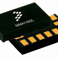
MMA7455LT Freescale Semiconductor, MMA7455LT Datasheet - Page 9

MMA7455LT
Manufacturer Part Number
MMA7455LT
Description
Board Mount Accelerometers 3-AXIS DIGITAL 2 4 8G
Manufacturer
Freescale Semiconductor
Datasheet
1.MMA7455LT.pdf
(35 pages)
Specifications of MMA7455LT
Sensing Axis
X, Y, Z
Acceleration
2 g, 4 g, 8 g
Supply Voltage (max)
3.6 V
Supply Voltage (min)
2.4 V
Supply Current
400 uA
Maximum Operating Temperature
+ 85 C
Minimum Operating Temperature
- 40 C
Sensitivity
64 LSB/g
Package / Case
LGA-14
Output Type
Digital
Acceleration Range
± 2g, ± 4g, ± 8g
No. Of Axes
3
Sensor Case Style
LGA
No. Of Pins
14
Supply Voltage Range
2.4V To 3.6V
Operating Temperature Range
-40°C To +85°C
Filter Terminals
SMD
Rohs Compliant
Yes
Ic Interface Type
I2C, SPI
Lead Free Status / RoHS Status
Lead free / RoHS Compliant
Available stocks
Company
Part Number
Manufacturer
Quantity
Price
Company:
Part Number:
MMA7455LT
Manufacturer:
FREESCALE
Quantity:
18 300
Part Number:
MMA7455LT
Manufacturer:
FREESCALE
Quantity:
20 000
FEATURES
Self-Test
The sensor provides a self-test feature that allows the verification of the mechanical and electrical integrity of the accelerometer
at any time before or after installation. This feature is critical in applications such as hard disk drive protection where system in-
tegrity must be ensured over the life of the product. When the self-test function is initiated through the mode control register ($16),
accessing the “self-test” bit, an electrostatic force is applied to each axis to cause it to deflect. The Z-axis is trimmed to deflect
1g. This procedure assures that both the mechanical (g-cell) and electronic sections of the accelerometer are functioning.
g-Select
The g-Select feature enables the selection between 3 acceleration ranges for measurement. Depending on the values in the
Mode control register ($16), the MMA7455L’s internal gain will be changed allowing it to function with a 2g, 4g or 8g measurement
sensitivity. This feature is ideal when a product has applications requiring two or more acceleration ranges for optimum perfor-
mance and for enabling multiple functions. The sensitivity can be changed during the operation by modifying the two GLVL bits
located in the mode control register.
$16: Mode Control Register (Read/Write)
Standby Mode
This digital output 3-axis accelerometer provides a standby mode that is ideal for battery operated products. When standby mode
is active, the device outputs are turned off, providing significant reduction of operating current. When the device is in standby
mode the current will be reduced to 2.5 µA typical. In standby mode the device can read and write to the registers with the I
SPI available, but no new measurements can be taken in this mode as all current consuming parts are off. The mode of the device
is controlled through the mode control register by accessing the two mode bits as shown in
Measurement Mode
The device can read XYZ measurements in this mode. The pulse and threshold interrupts are not active. During measurement
mode, continuous measurements on all three axes enabled. The g-range for 2g, 4g, or 8g are selectable with 8-bit data and the
g-range of 8g is selectable with 10-bit data. The sample rate during measurement mode is 125 Hz with 62.5 BW filter selected.
The sample rate is 250 Hz with the 125 Hz filter selected. Therefore, when a conversion is complete (signaled by the DRDY flag),
the next measurement will be ready.
When measurements on all three axes are completed, a logic high level is output to the DRDY pin, indicating “measurement data
is ready.” The DRDY status can be monitored by the DRDY bit in Status Register (Address: $09). The DRDY pin is kept high until
one of the three Output Value Registers are read. If the next measurement data is written before the previous data is read, the
DOVR bit in the Status Register will be set. Also note that in measurement mode, level detection mode and pulse detection mode
are not available.
By default all three axes are enabled. X and/or Y and/or Z can be disabled. There is a choice between detecting an absolute
signal or a positive or negative only signal on the enabled axes. There is also a choice between doing a detection for motion
where X or Y or Z > Threshold vs. doing a detection for freefall where X & Y & Z < Threshold.
Sensors
Freescale Semiconductor
D7
--
0
DRPD
D6
0
Table 5. Configuring the g-Select for 8-bit output using Register $16 with GLVL[1:0] bits
Table 6. Configuring the Mode using Register $16 with MODE[1:0] bits
GLVL [1:0]
SPI3W
D5
0
00
01
10
MODE [1:0]
STON
D4
00
01
10
11
0
GLVL[1]
D3
0
g-Range
8g
2g
4g
GLVL[0]
Pulse Detection Mode
Level Detection Mode
Measurement Mode
D2
0
Standby Mode
Function
MODE[1]
D1
0
Sensitivity
16 LSB/g
64 LSB/g
32 LSB/g
Table
6.
MODE[0]
D0
0
MMA7455L
Function
Default
Bit
2
C/
9


