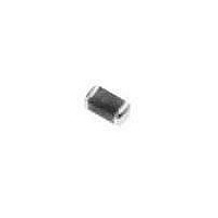
ERT-J1VR103J Panasonic, ERT-J1VR103J Datasheet - Page 6

ERT-J1VR103J
Manufacturer Part Number
ERT-J1VR103J
Description
Thermistors - NTC 10K OHM 5%
Manufacturer
Panasonic
Series
ERTr
Type
NTCr
Specifications of ERT-J1VR103J
Resistance
10 KOhms
Tolerance
5 %
Termination Style
SMD/SMT
Operating Temperature Range
- 30 C to + 125 C
Dimensions
0.80 mm W x 1.60 mm L x 0.8 mm H
Power Rating
0.4 W
Temperature Coefficient
4250 k PPM / C
Package / Case
0603
Lead Free Status / RoHS Status
Lead free / RoHS Compliant
Available stocks
Company
Part Number
Manufacturer
Quantity
Price
Part Number:
ERT-J1VR103J
Manufacturer:
PANASONIC/松下
Quantity:
20 000
Fig.2 Recommended Amount of Solder
Fig.3 Component Layout
Table 2 Application Examples of Solder Resist
Narrow Spacing
between Chip
Components
Radial Components
are directly
connected to Chip
Components
Common lands
(chassis,etc.)are
close to Chip
Components.
2.3 Component Layout
2.4 Mounting Density and Spaces
2.5 Applications of Solder Resist
Excess amounts of solder may cause large
mechanical stresses to the Thermistors/components.
of
(2) Recommended Amount of Solder:
When placing/mounting the Thermistors/components
near an area which is apt to bend or near a grid
groove on the PC board, it is advisable to
have both electrodes subjected to uniform
stresses, or toposition the components
electrodes at right angles to the grid groove or
bending line.
Placements in too narrow spaces between
components may cause ÒSolder BridgesÓ, during
soldering. The minimum space between components
shall be 0.5 mm in view of the positioning tolerances
of the mounting machines and the dimensional
tolerances of the components and PC boards.
Applications of Solder resist are effective in
preventing solder bridges and controlling amounts
solder on PC boards. (As shown in Table 2)
As shown in Fig.2
Application Examples
Recommended
Solder Bridges
Examples of
n
1 Storage
2 Adhesives for Mounting
3 Chip Mounting Consideration
Fig.4 Bottom dead point height of the vacuum nozzle
Fig.5 Backup pins
(a) Improper
(4) The amount of adhesive shall be such
(3) The Thermistors should be used within 6 months.
Precautions for Assembly
(1) The Thermistors shall not be stored under
(2) The solderability of the external electrodes
(1) The viscosity of an adhesive for mountings
(2) If the adhesive is too low in its viscosity,
(3) The adhesives shall not be corrosive or
(5) Adhesives for mountings can be cured by
In mounting the Thermistors/components on a
printed circuit board, any bending and expanding
force against them shall be kept minimum
to prevent being damage or cracking. The
following precautions and recommendations shall
be observed carefully in the process;
(1) Maximum stroke of the vacuum nozzle shall be
(2) Maximum stroke of the nozzle shall be adjusted
(3) The printed circuit board shall be supported by
Check solderability before use.
shall be such that the adhesive does not flow
off of the land during itÕs curing.
mounted components may be out of alignment
after or during soldering.
chemically active to the mounted components
and the PC boards.
that the adhesive does not flow off of the
land or cause the component.
ultraviolet or infrared radiation. In order to prevent
the terminal electrodes of the Thermistors from
oxidizing. The curing shall be done at conditions
of 160 ¡C max., for 2 minutes max.
adjusted so that the pushing force to the printed
circuit board should be limited to a static load of 1
to 3 N. (See Fig.4)
so that the maximum bending of printed circuit
board does not exceed 0.5 mm. (See Fig.4)
means of adequate supporting pins as shown in
Fig.5-(b).
severe conditions of high temperature and/or
humiditiy .Store them indoors under at 5-40 ¡C
and 20-70% RH.
maybe degraded if the Thermistors are
stored where they are exposed to high
humidities, dust or harmful gases such as
hydrogen sulfide, sulfuric acid, hydrogen
chlorine or ammonia. Avoid exposing the
Thermistor to heat or direct sunlight.
Otherwise the packing materials may be
deformed or the Thermistors may stick together
that would cause problems during mounting.
NTC Thermistors (Chip Type)
(b) Proper


