ULE-5/12-D24P-C Murata Power Solutions Inc, ULE-5/12-D24P-C Datasheet - Page 17
ULE-5/12-D24P-C
Manufacturer Part Number
ULE-5/12-D24P-C
Description
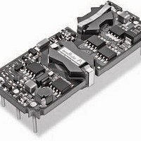
DC/DC Converters & Regulators 60W 24V to 5V 12A POSITVE POLARITY
Manufacturer
Murata Power Solutions Inc
Series
ULEr
Type
Step Downr
Specifications of ULE-5/12-D24P-C
Output Power
60 W
Input Voltage Range
18 V to 36 V
Input Voltage (nominal)
24 V
Number Of Outputs
1
Output Voltage (channel 1)
5 V
Output Current (channel 1)
12 A
Isolation Voltage
2.25 KV
Package / Case Size
Eighth Brick
Product
Isolated
Output Current
12A
Input Voltage
24V
Output Voltage
5V
Screening Level
Industrial
Product Length (mm)
58.4mm
Product Depth (mm)
22.9mm
Mounting Style
Through Hole
Pin Count
8
Package / Case
1/8-Brick
Lead Free Status / RoHS Status
Lead free / RoHS Compliant
Other names
ULE-5/12-D24P-C


Post Refl ow Procedures
After successful solder refl ow, be sure to completely clean and dry your assem-
bled boards using a recommended wash solution and dryer. Failure to remove all
fl ux may cause long term deterioration of on-board conductors and components.
And, traces of contaminants which are not removed may reduce isolation volt-
ages or risk a safety hazard. Be aware that low remaining concentrations of fl ux
or other assembly compounds can be very diffi cult to detect by eye.
Pick and Place pcb Mounting
The main issues here are pad area, orientation, positioning accuracy, vacuum
pickup and coplanarity. Murata Power Solutions recommends that pcb pads to
interface with the DC/DC converter should be sized as shown in the diagram
below. The pads footprint accommodates the positioning accuracy of your SMT
equipment and manufactured tolerances of the DC/DC mounting leads.
250
200
150
100
50
0.130 TYP.
(3.30)
SMT UNIT
0.020 (0.51)
Figure 12. Recommended SMT Mounting Pad Dimensions
(When the Heat-shield temperature exceeds +250°C,
Z1
100
Z2
Figure 11. Recommended Solder Profi le
DIMENSIONS ARE IN INCHES (MM)
0.300 TYP.
Z3
(7.62)
the air within is 50°C cooler)
2.340 (59.44)
1.975 (50.17)
200
PCB
Z4
Z5
SMT LEAD
Z6
300
0.150 TYP.
(3.81)
Z7
Seconds
Copper Pad
400
www.murata-ps.com
500
0.020 REF.
(0.51)
0.183
(4.65)
Heat Shield
Test Board
Air Under Shield
600
viewable by your SMT imaging system. Observing from the bottom, your SMT
imaging camera should fi nd these marks to identify the converter and verify pin
1. On most pick-and-place systems, during head transit, the imaging system will
automatically fi ne tune the end mounting position of the converter using image
comparisons from these fi ducials or other reference marks you have chosen.
systems have a one inch or less observing area since most SMT parts are con-
siderably smaller than these converters. You may prefer to train your imaging
system to use a corner of the converter or an I/O lead.
In the remote possibility that the fi ducials may have changed position with a PC
board revision, you should not mix different date lots on any one production as-
sembly session. In addition, to avoid non-recognition or misplacement of the con-
verter, retrain your imaging system at the beginning of each series of assembly
sessions. There may be tiny variations in the absolute position from unit to unit.
not rely on the inkjet marking on the heat shield to verify proper orientation.
Use the pin 1 notch instead.
very fl at mounting leads (see coplanarity specs) however your host pcb must
also be fl at for a successful mounting. Be aware of possible warping of the pcb
under heat gradients and/or humidity conditions. The solder paste will tolerate
a small amount of mismatch and will tend to “wet” the entire pad area by
capillary action if the temperatures are correct.
for the weight and size of the DC/DC converter. Note that units with heatsinks
are slightly heavier. Tests at Murata Power Solutions have shown that excellent
acceleration and transit head speed are available for these converters if the
collet size is proper and the vacuum is suffi cient. When positioning the vacuum
collet, use the geometric center of the heat shield as the pickup area since the
center of gravity is very close.
Soldering
Refl ow technology works well for small parts. However, larger components
such as these DC/DC’s with higher thermal mass may require additional refl ow
time (but not enough to disturb smaller parts also being refl owed concurrently
with the DC/DC). When this is combined with higher temperature lead-free sol-
ders (or solders with reduced heavy metals), there is increased risk of reheat-
ing components inside the DC/DC enough so that they either change positions
(and possibly stop functioning) or the components are damaged by the heat.
On the bottom of the converter, the ULE series include optical fi ducial marks
The fi ducial marks are placed fairly close together because many imaging
The fi ducial marks will remain identical within any date code lot of converters.
If you use a camera above the pcb after placement on the solder paste, do
Coplanarity: Murata Power Solutions manufactures these converters with
Vacuum Pickup: Select the vacuum collet on your SMT placement system
are oriented in the same direction. See the diagram below. For
the ULE series, a notch is placed on the top of the case (on the
removal tabs) to indicate the pin 1 position. You should visually
inspect the tray to be sure of this orientation.
camera which must be trained to recognize the orientation of
the converter before it is assembled onto the host PC board.
This “training” locates and identifi es prominent, dimensionally
stable landmarks such as the board corners or fi ducial marks.
Orientation: When loaded into JEDEC trays, the converters
Most pick-and-place automatic assembly systems use a
Isolated, High Density, Eighth-Brick
11 May 2011
1.25–20 Amp, DC/DC Converters
MDC_ULE Series.E01 Page 17 of 26
email: sales@murata-ps.com
ULE Series
Related parts for ULE-5/12-D24P-C
Image
Part Number
Description
Manufacturer
Datasheet
Request
R

Part Number:
Description:
DC/DC TH 12A 24-5V E-Brick
Manufacturer:
Murata Power Solutions Inc
Datasheet:
Part Number:
Description:
DC/DC SM 12A 24-5V E-Brick
Manufacturer:
Murata Power Solutions Inc
Part Number:
Description:
DC/DC TH 12A 48-5V E-Brick
Manufacturer:
Murata Power Solutions Inc
Part Number:
Description:
DC/DC SM 12A 48-5V E-Brick
Manufacturer:
Murata Power Solutions Inc
Part Number:
Description:
DC/DC TH 12A 48-5V E-Brick
Manufacturer:
Murata Power Solutions Inc
Part Number:
Description:
DC/DC SM 12A 48-5V E-Brick
Manufacturer:
Murata Power Solutions Inc

Part Number:
Description:
DC/DC SM 12A 24-5V E-Brick
Manufacturer:
Murata Power Solutions Inc
Part Number:
Description:
DC/DC Converters & Regulators 50W 12V to 5V 10A POSITVE POLARITY
Manufacturer:
Murata Power Solutions Inc
Datasheet:
Part Number:
Description:
DC/DC SM 10A 12-5V E-Brick
Manufacturer:
Murata Power Solutions Inc
Part Number:
Description:
DC/DC TH 10A 12-5V E-Brick
Manufacturer:
Murata Power Solutions Inc
Part Number:
Description:
DC/DC TH 20A 24-2.5V E-Brick
Manufacturer:
Murata Power Solutions Inc
Datasheet:

Part Number:
Description:
Transformers 5Vin 5Vout 200mA 4000Vdc 1:1.33 turn
Manufacturer:
Murata Power Solutions Inc
Datasheet:
Part Number:
Description:
POWER SUPPLY
Manufacturer:
Murata Power Solutions Inc
Datasheet:

Part Number:
Description:
DPM LED MINI 2VDC 3.5DIG LP RED
Manufacturer:
Murata Power Solutions Inc
Datasheet:

Part Number:
Description:
CONV DC/DC 1W 5VIN 5VOUT SIP SGL
Manufacturer:
Murata Power Solutions Inc
Datasheet: