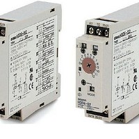
H3DE-M2AC/DC24-230 Omron, H3DE-M2AC/DC24-230 Datasheet - Page 7

H3DE-M2AC/DC24-230
Manufacturer Part Number
H3DE-M2AC/DC24-230
Description
Stopwatches / Timers MULTI-FUN SOLID STAT
Manufacturer
Omron
Type
Multifunctionr
Specifications of H3DE-M2AC/DC24-230
Timing Range
0.1 s to 120 Hrs
Supply Voltage
25 VAC to 230 VAC, 24 VDC to 28 VDC
Accuracy
+/- 1 %
Current Rating (max)
5 A
Display Type
Hand Dial
Operating Temperature Range
- 10 C to + 55 C
Termination Style
Screw
Time Range
0.1 Sec. To 120 Hr.
Supply Voltage Max
230VDC
Time Range Max
120h
Switch Function
DPDT
Time Range Min
0.1s
Supply Voltage Min
24VDC
Lead Free Status / RoHS Status
Lead free / RoHS Compliant
Lead Free Status / RoHS Status
Lead free / RoHS Compliant, Lead free / RoHS Compliant
J BASIC OPERATION
Selector Setting
The selectors can be turned clockwise and counterclockwise to
select the desired time unit, time scale, or operating mode.
Each selector has a snap mechanism that secures the selector at
a given position. Set the selector at a position at which it is
secured. Do not set it midway between two securing positions or
a malfunction could result from improper setting.
Operating Mode Selection
The H3DE-M/-S can be set to any one of the operating modes A
to J. Turn the operating mode selector with a screwdriver until the
desired operating mode (A, B, B2, C, D, E, G, or J for the
H3DE-M and A, B2, E, or J for the H3DE-S) appears in the
operating mode display window located below the selector.
J TIMING CHART
Note: 1. The minimum power reset time is 0.1 s and the minimum signal input time is 0.05 s.
Operating
mode
A: ON-delay
2. The letter “t” in the timing charts stands for the set time and “t- -a” means that the period is less than the time set.
Timing chart
Power (A
Start (B
(See Note.)
Output relay: NC
15 and 16
(25 and 26)
Output relay: NO
(output indicator)
15 and 18
(25 and 28)
Power indicator
Operating mode selector
1
1
and A
and A
2
)
2
)
t
Groove for
screwdriver
Operating mode
display window
A
(This table continues on the next page.)
t- -a
Time Unit and Time Scale Selection
The desired time unit (sec, min, hrs, or 10h) can be displayed in
the time unit display window above the time setting dial by
turning the time unit selector located at the upper right corner of
the front panel. The time scale (0.1 or 1) is selected with the time
scale selector at the upper left corner of the front panel. It
appears in the scale range display window above the selector.
Scale range display
window
t
Scale range
selector
Time unit selector
Time unit display window
Output
Power
*
** Start input is invalid while the Timer is in opera-
Basic operation
Start
*
For power-on operation, impose voltage to the
Start input. The Timer starts operating at the
moment the power is turned on.
tion.
**
t


