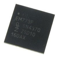
EM773FHN33,551 NXP Semiconductors, EM773FHN33,551 Datasheet - Page 36

EM773FHN33,551
Manufacturer Part Number
EM773FHN33,551
Description
IC ENERGY METER ARM 32VQFN
Manufacturer
NXP Semiconductors
Datasheet
1.EM773FHN33551.pdf
(45 pages)
Specifications of EM773FHN33,551
Core Processor
ARM Cortex-M0
Core Size
32-Bit
Speed
48MHz
Connectivity
I²C, SPI, UART/USART
Peripherals
Brown-out Detect/Reset, POR, WDT
Number Of I /o
25
Program Memory Size
32KB (32K x 8)
Program Memory Type
FLASH
Ram Size
8K x 8
Voltage - Supply (vcc/vdd)
1.8 V ~ 3.6 V
Oscillator Type
Internal
Operating Temperature
-40°C ~ 85°C
Package / Case
32-VQFN Exposed Pad
Output Voltage
3.6 V
Output Current
20 mA
Output Power
1.5 W
Input Voltage
1.8 V to 3.6 V
Switching Frequency
48 MHz
Operating Temperature Range
- 40 C to + 85 C
Mounting Style
SMD/SMT
Duty Cycle (max)
50 %
Number Of Outputs
10
Lead Free Status / RoHS Status
Lead free / RoHS Compliant
Eeprom Size
-
Data Converters
-
Lead Free Status / Rohs Status
Lead free / RoHS Compliant
Other names
568-5213
NXP Semiconductors
11. Application information
EM773
Objective data sheet
11.1 XTAL input
The input voltage to the on-chip oscillators is limited to 1.8 V. If the oscillator is driven by a
clock in slave mode, it is recommended that the input be coupled through a capacitor with
C
capacitor to ground C
mode, a minimum of 200 mV(RMS) is needed.
In slave mode the input clock signal should be coupled by means of a capacitor of 100 pF
(Figure
corresponds to a square wave signal with a signal swing of between 280 mV and 1.4 V.
The XTALOUT pin in this configuration can be left unconnected.
External components and models used in oscillation mode are shown in
Table 13
and the capacitances C
fundamental mode oscillation (the fundamental frequency is represented by L, C
R
not be larger than 7 pF. Parameters F
manufacturer (see
Fig 21. Slave mode operation of the on-chip oscillator
i
S
= 100 pF. To limit the input voltage to the specified range, choose an additional
). Capacitance C
21), with an amplitude between 200 mV(RMS) and 1000 mV(RMS). This
and
Table
All information provided in this document is subject to legal disclaimers.
Table
P
14. Since the feedback resistance is integrated on chip, only a crystal
in
g
Rev. 1 — 1 September 2010
which attenuates the input voltage by a factor C
Figure 22
X1
13).
and C
X2
represents the parallel package capacitance and should
need to be connected externally in case of
XTALIN
EM773
C i
100 pF
OSC
, C
L
, R
em773_002aae788
C g
S
and C
P
are supplied by the crystal
Energy metering IC
i
/(C
© NXP B.V. 2010. All rights reserved.
Figure 22
i
+ C
EM773
g
). In slave
L
and
and in
36 of 45


